

Testing the resistance of a wire with a multimeter sounds simple on paper, but it reveals far more than most people realize. A resistance reading can expose hidden wiring damage, poor electrical connections, corrosion, overheating, insulation problems, and even future electrical failures waiting to happen. Whether you are troubleshooting home wiring, diagnosing automotive electrical systems, repairing electronics, or maintaining industrial equipment, understanding resistance measurements can save time, money, and frustration.
Electricity behaves a lot like water flowing through a pipe. If the pipe is narrow, clogged, or damaged, water struggles to move freely. Resistance works the same way inside a wire. High resistance acts like a blockage that restricts electrical current flow, creates heat, reduces efficiency, and can eventually damage equipment. A multimeter helps you uncover those invisible restrictions before they become major problems.
Modern digital multimeters make resistance testing easier than ever. Even entry-level meters can accurately detect continuity problems, open circuits, short circuits, and excessive resistance levels. Industry safety guides from sources like emphasize that resistance measurements are one of the most effective ways to evaluate the condition of conductors and electrical components.
Before diving into the actual testing process, it helps to understand how resistance works and why every reading matters.
Understanding Resistance in Electrical Wires
What Electrical Resistance Actually Means
Electrical resistance is the opposition a material gives to the flow of electric current. Every wire has some resistance, even excellent conductors like copper and aluminum. The goal is not to eliminate resistance completely because that is impossible in real-world electrical systems. Instead, the objective is to keep resistance low enough for current to flow efficiently and safely.
R=VIR=frac{V}{I}
VsV_s
<0″ name=”V_s”>V
RR
<0″ name=”R”><5″ step=”any” type=”range” value=”6″>
ΩOmega
I=VsR=12.0 V6.0 Ω=2.00 AI = frac{V_s}{R} = frac{12.0,mathrm{V}}{6.0,Omega} = 2.00,mathrm{A}
Source voltage in volts drives the same loop current through the whole one-resistor circuit, and resistance in ohms limits that current, using Ohm’s law. Resistance is constrained from 0.5 to 20 ohms. The resistor’s inner pipe narrows as a visual cue for higher resistance, not as a literal mechanical clamp. The blue arrow and resistor markers are qualitative conventional current cues, not microscopic charge-speed measurements. In this one-resistor model, the source voltage equals the resistor voltage drop; heating, power limits, and non-ohmic behavior are not shown.Vs = 12.0 V+-R = 6.0 ΩI = 2.00 A
This relationship, known as Ohm’s Law, explains why resistance matters so much in electrical systems. If resistance increases unexpectedly, current flow decreases or heat production rises. That is why electricians and technicians routinely check resistance levels when diagnosing wiring issues.
When you measure a wire with a multimeter, the meter sends a tiny electrical current through the conductor and calculates how much opposition exists. If the wire is healthy, the reading will usually be very low, often close to zero ohms for short copper wires. If the wire is damaged, corroded, partially broken, or poorly connected, resistance rises noticeably.
Professional electricians often compare resistance testing to taking a person’s pulse. A quick measurement may instantly reveal whether a system is healthy or in distress. Even small changes can signal deeper problems hidden beneath insulation or inside connectors.
Why Resistance Matters in Wiring Systems
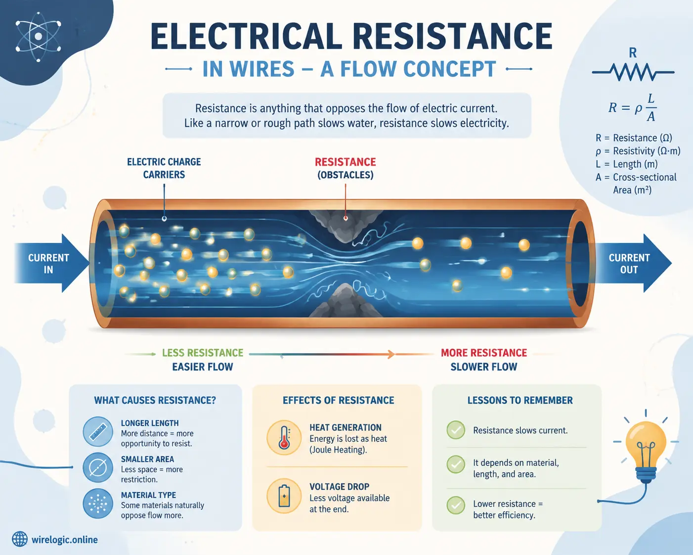
Resistance directly affects energy efficiency, electrical safety, and equipment performance. Excessive resistance creates heat, and heat is one of the leading causes of electrical failure. According to electrical safety resources from , resistance increases over time due to dirt, wear, corrosion, and loose electrical contacts.
Think about a garden hose with a kink in it. Water still flows, but pressure drops and turbulence increases. High resistance acts similarly inside a wire. The current struggles to pass efficiently, causing voltage drops and wasted energy. In severe cases, overheating can melt insulation or start fires.
Resistance testing is also important because many wiring problems remain invisible during visual inspection. A wire might look perfect on the outside while hidden corrosion or internal strand damage increases resistance dramatically. Measuring resistance gives you insight into the wire’s internal condition without cutting it open.
Automotive technicians, industrial maintenance workers, and home electricians all rely heavily on resistance testing because it helps detect faults before total failure occurs. Preventive testing can stop costly downtime and dangerous electrical hazards long before smoke or sparks appear.
What Resistance Reveals About a Wire’s Condition
Healthy Wire vs Damaged Wire Readings
A healthy wire generally produces a low resistance reading because electricity moves freely through the conductor. The exact reading depends on the wire’s length, thickness, and material, but short copper wires often measure close to zero ohms.
A damaged wire tells a different story. If the wire contains broken strands, corrosion, oxidation, or loose terminals, the resistance rises. Sometimes the increase is gradual, while severe damage may create an open circuit that displays “OL” or infinite resistance on the meter.
Here is a simple comparison table:
| Wire Condition | Typical Resistance Reading | Meaning |
|---|---|---|
| Healthy short copper wire | Near 0 Ω | Good continuity |
| Long wire | Slightly higher Ω | Normal due to length |
| Corroded wire | Higher than expected Ω | Restricted current flow |
| Broken wire | OL or infinite Ω | Open circuit |
| Loose connection | Fluctuating Ω | Unstable electrical path |
A fluctuating resistance reading is often one of the clearest warning signs of intermittent damage. If the value jumps around while the wire is moved, bent, or touched, internal conductor damage may exist.
How Corrosion and Heat Affect Resistance
Corrosion acts like rust inside an electrical pathway. Oxidation on copper or aluminum connections creates microscopic barriers that force electricity to work harder. The result is increased resistance and additional heat buildup.
Heat itself also changes resistance. As conductors become hotter, resistance naturally rises. This is why overloaded circuits often worsen over time. More heat creates more resistance, and more resistance creates even more heat. It becomes a destructive cycle.
In automotive wiring, battery terminals are common high-resistance trouble spots. Even a thin layer of corrosion can cause hard starting, dim headlights, or charging problems. In homes, loose outlets and overheated junction boxes often develop resistance-related issues that slowly damage surrounding materials.
Experts often describe high resistance as a silent electrical killer because systems may continue functioning while hidden damage spreads internally. That is why regular resistance testing is valuable for preventive maintenance.
Getting the Multimeter Ready Before Testing
Identifying the Correct Meter Settings
Before measuring resistance, the multimeter must be configured correctly. Most digital multimeters include a resistance mode identified by the omega symbol:
ΩOmega
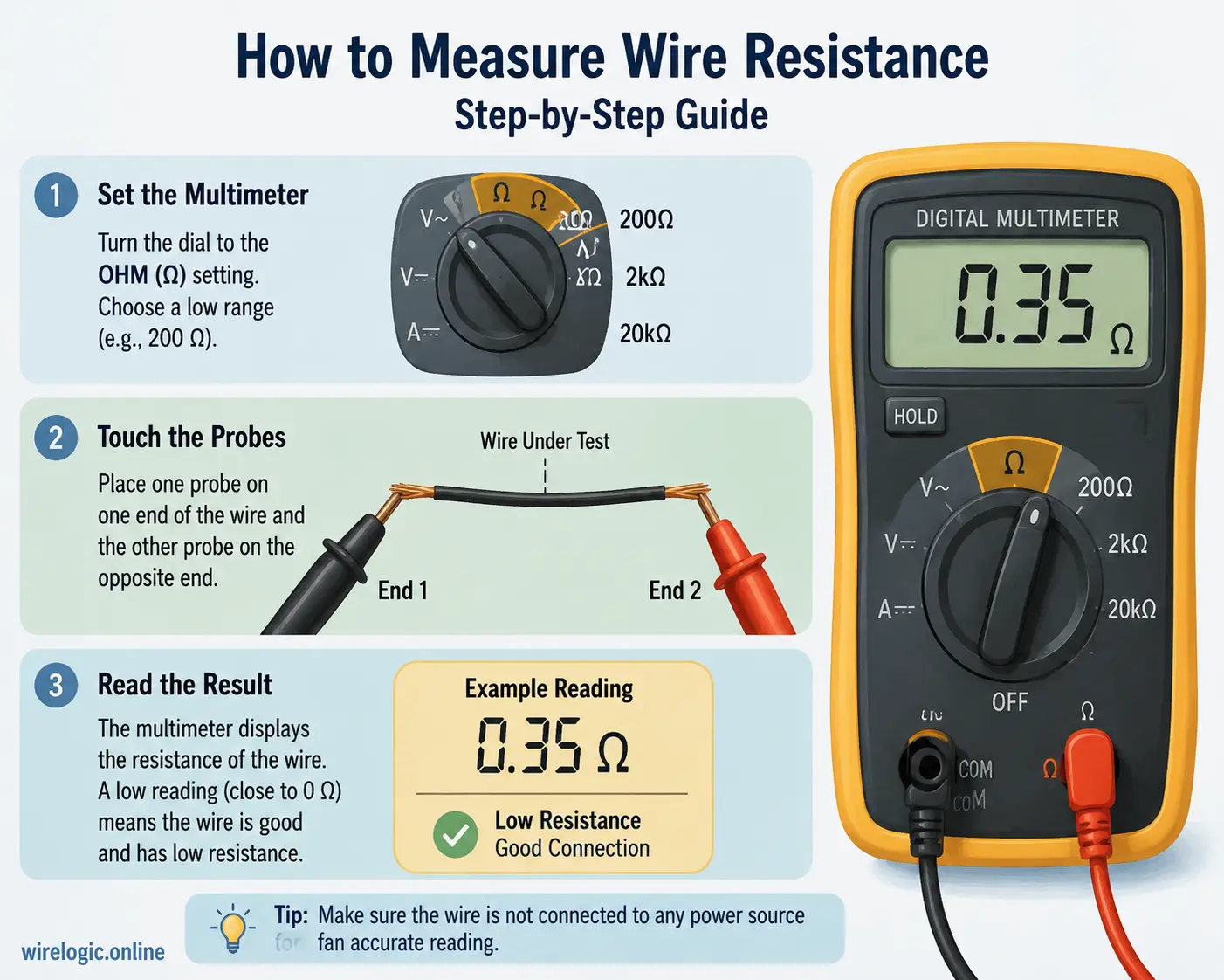
Turn the selector dial to the resistance setting before touching the probes to the wire. If your meter has auto-ranging capability, it automatically selects the proper range. Manual-range meters require you to choose a suitable resistance scale yourself.
Industry testing guides from recommend starting with a higher range if the expected value is unknown.
The test leads should be connected properly:
- Black lead into the COM port
- Red lead into the VΩ port
Incorrect lead placement is one of the most common mistakes beginners make. Some users accidentally leave the probe in the current-testing socket, which can create dangerous conditions and inaccurate readings.
Inspecting Multimeter Leads for Accuracy
Your test leads matter more than many people think. Damaged or low-quality probes can introduce resistance errors into measurements. Electrical testing guides recommend inspecting leads regularly for cracks, loose connectors, or worn insulation.
A quick way to verify lead condition is by touching the probe tips together. The reading should be extremely low, usually close to zero ohms. If the meter shows unusually high resistance while the probes touch directly, the leads may be damaged or dirty.
For very small resistance measurements, lead resistance itself becomes important. Two-wire testing methods measure both the wire resistance and the probe resistance together.
Professional technicians sometimes use four-wire Kelvin testing for extremely precise low-resistance measurements, but standard multimeters remain perfectly adequate for most household and automotive troubleshooting tasks.
Why the Wire Must Be Disconnected from Power First
Safety Risks of Measuring Live Circuits
One of the most important rules in resistance testing is simple: never measure resistance on an energized circuit.
Electrical safety references repeatedly warn that resistance mode uses the meter’s internal battery to inject a small testing current into the circuit. External voltage interferes with this process and can damage the multimeter or injure the user.
Imagine trying to measure the speed of a moving bicycle while someone else is pushing it from behind. The results become meaningless because outside forces interfere with the measurement. Live voltage creates the same problem during resistance testing.
More importantly, energized circuits can expose the operator to electric shock hazards. Even low-voltage systems may spark unexpectedly if improper settings are used.
How Live Voltage Causes False Readings
Live voltage changes the behavior of the meter completely. Instead of measuring the wire’s actual resistance, the meter receives conflicting electrical signals from both its internal battery and the active circuit voltage.
This can cause:
- False low resistance readings
- False high resistance readings
- Unstable readings
- Meter overload warnings
- Internal meter damage
Professional electricians often isolate the wire completely from the circuit before testing. Disconnecting both ends ensures parallel pathways do not influence the measurement.
Choosing the Correct Resistance Range on the Meter
Manual Range vs Auto Range Multimeters
Modern digital multimeters come in two main varieties:
- Auto-ranging
- Manual-ranging
Auto-ranging meters automatically choose the correct scale for the measurement. They are beginner-friendly and reduce setup mistakes. Manual-range meters require users to select a resistance range manually, such as 200 Ω, 2 kΩ, or 20 MΩ.
If the selected range is too low, the display may show:
- OL
- 1
- Infinite resistance
If the range is too high, small readings may lose precision.
Understanding OL, Zero, and Low-Ohm Readings
Resistance readings can tell a detailed story once you understand the display symbols.
| Display Reading | Meaning |
|---|---|
| 0 Ω or near zero | Strong continuity |
| OL | Open circuit |
| Fluctuating values | Intermittent connection |
| Very high Ω | Corrosion or poor conductor |
A near-zero reading usually means the wire conducts electricity properly. An OL reading suggests the conductor path is broken somewhere.
Step-by-Step Process to Measure Wire Resistance
Preparing the Wire for Testing
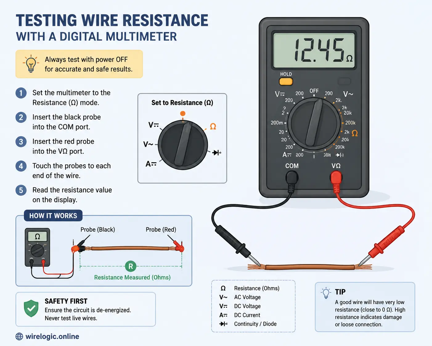
Start by disconnecting all power sources completely. Remove batteries, unplug devices, or switch off circuit breakers before proceeding.
Expose clean conductor surfaces if needed. Dirt, paint, oxidation, or insulation residue can interfere with probe contact.
If testing installed wiring, isolate the wire from the rest of the circuit whenever possible. Parallel connections may distort the measurement.
Placing the Probes Correctly
Touch one probe to each end of the wire. Probe polarity does not matter in resistance mode because resistance has no positive or negative direction.
Maintain steady contact during testing. Loose probe contact may create fluctuating readings that mimic wiring faults.
For long wires, gently flexing the cable while watching the meter can reveal intermittent breaks hidden inside the insulation.
Reading and Interpreting the Display
Once the probes contact the conductor, the meter stabilizes and displays the resistance value.
y=0.02xy=0.02x
.graphable-function-chartjs {
position: relative;
overflow: hidden;
touch-action: none;
}
.graphable-function-chartjs-tooltip {
position: absolute;
z-index: 1;
border-radius: 9px;
background: rgb(0 0 0 / 90%);
color: white;
font-size: 11px;
font-weight: 600;
line-height: 14px;
padding: 6px 12px;
text-align: center;
white-space: nowrap;
pointer-events: none;
}
.graphable-function-chartjs-guide {
position: absolute;
top: 0;
bottom: 0;
border-left: 1px dashed var(–border-heavy);
pointer-events: none;
}
.graphable-function-chartjs-hover-point {
position: absolute;
width: 8px;
height: 8px;
margin-left: -4px;
margin-top: -4px;
border: 1.5px solid white;
border-radius: 9999px;
background: black;
pointer-events: none;
}
.graphable-function-chartjs-reset {
position: absolute;
left: 12px;
bottom: 12px;
display: inline-flex;
align-items: center;
justify-content: center;
z-index: 2;
width: 32px;
height: 32px;
border: 1px solid var(–border-light);
border-radius: 9999px;
background: var(–bg-primary);
color: var(–text-primary);
box-shadow: 0 2px 8px rgb(0 0 0 / 8%);
padding: 0;
transition: opacity 160ms ease, transform 160ms ease;
}
Resistance generally increases with wire length, which is why longer conductors naturally show larger values. Small variations are normal, but sudden jumps or unstable readings often indicate trouble.
How Wire Length and Thickness Affect the Reading
Why Longer Wires Have Higher Resistance
Longer wires contain more material for electrons to travel through, so resistance naturally rises with distance.
R=ρLAR=rhofrac{L}{A}
This equation shows that resistance depends on:
- Material resistivity
- Length
- Cross-sectional area
A 100-foot wire will always measure higher resistance than a 10-foot wire made from the same material and thickness.
How Wire Gauge Changes Electrical Flow
Wire thickness also plays a major role. Thick wires have lower resistance because they provide a larger pathway for electrons.
Thin wires restrict current flow more aggressively and heat up faster under load. This is why high-current applications use larger gauge conductors.
Here is a simplified comparison:
| Wire Gauge | Relative Resistance |
|---|---|
| Thick wire | Lower resistance |
| Thin wire | Higher resistance |
Understanding these relationships prevents misdiagnosing normal readings as faults.
Signs That Point to High Resistance Problems
Overheating and Voltage Drop
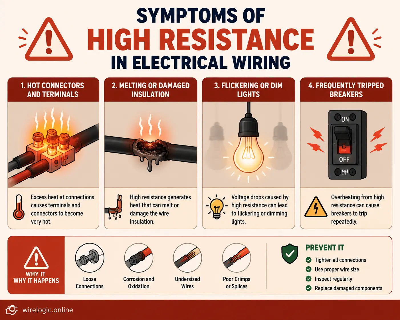
High resistance often creates excessive heat at connectors, terminals, or damaged wire sections.
Symptoms include:
- Warm outlets
- Melted insulation
- Burning smells
- Hot connectors
- Voltage drops
When resistance rises, electrical energy converts into heat instead of useful work.
Flickering Devices and Weak Performance
High resistance can also cause:
- Flickering lights
- Weak motors
- Slow starters
- Battery charging issues
- Random electronic resets
Many intermittent electrical problems trace back to hidden resistance increases rather than total circuit failure.
Common Mistakes That Lead to Inaccurate Measurements
Testing Wires Inside Active Circuits
One of the biggest errors is testing resistance while the wire remains connected to powered equipment.
Parallel pathways can produce misleading readings because the meter measures multiple current paths simultaneously.
Ignoring Probe Resistance
Cheap or worn probes can add measurable resistance to low-ohm readings. Touching probes together before testing establishes a baseline reference.
For extremely small resistance measurements, probe resistance becomes especially important.
Using Resistance Readings to Spot Damaged Wiring
Diagnosing Breaks and Loose Connections
Resistance testing excels at identifying:
- Broken wires
- Loose terminals
- Corrosion
- Connector damage
- Partial conductor failures
A wire with internal strand damage may still conduct electricity but produce unstable resistance readings when flexed.
This is especially common in automotive harnesses, extension cords, and appliance cables exposed to repeated movement.
When to Replace a Wire Completely
A wire should usually be replaced if:
- Resistance is significantly higher than expected
- The reading fluctuates unpredictably
- Heat damage is visible
- Corrosion has spread deeply
- Insulation is brittle or cracked
Trying to “patch” severely damaged wiring often creates future reliability problems.
Conclusion
Learning how to measure resistance of a wire using a multimeter is one of the most valuable electrical troubleshooting skills anyone can develop. Resistance testing provides insight into conductor health, connection quality, circuit integrity, and hidden electrical damage long before catastrophic failure occurs.
A healthy wire typically shows low and stable resistance. Rising resistance levels often reveal corrosion, loose connections, broken strands, overheating, or internal conductor deterioration. By understanding how wire length, thickness, and material influence resistance, you can interpret readings accurately instead of guessing.
Safety remains critical throughout the process. Disconnecting power completely before testing protects both the operator and the multimeter itself. Proper meter setup, good probe contact, and correct range selection all contribute to reliable measurements.
Whether you are diagnosing automotive wiring, checking household circuits, repairing electronics, or maintaining industrial equipment, resistance measurements act like a window into the hidden condition of electrical systems. A few seconds with a multimeter can uncover problems invisible to the naked eye and help prevent expensive failures later.
FAQs
1. What is a normal resistance reading for a wire?
Most short copper wires measure very close to 0 ohms. Longer or thinner wires naturally show slightly higher resistance.
2. Why does my multimeter show OL when testing a wire?
An OL reading usually means the wire has an open circuit or break preventing electrical continuity.
3. Can I test resistance on a live circuit?
No. Resistance testing must only be performed on de-energized circuits to avoid inaccurate readings, safety hazards, and possible meter damage.
4. Does wire length affect resistance?
Yes. Longer wires have higher resistance because electrons must travel through more conductive material.
5. Why do resistance readings fluctuate?
Fluctuating readings often indicate loose connections, damaged conductors, dirty contacts, or unstable probe placement.

Colt Marlowe is a 29-year-old American content writer based in Boise, Idaho. He specializes in technology, digital tools, and online business topics, combining years of research with practical experience to produce clear, trustworthy articles. As a contributor to wirelogic.online, he focuses on creating well-researched, reader-friendly content that emphasizes accuracy, transparency, and long-term value for audiences seeking reliable information.