
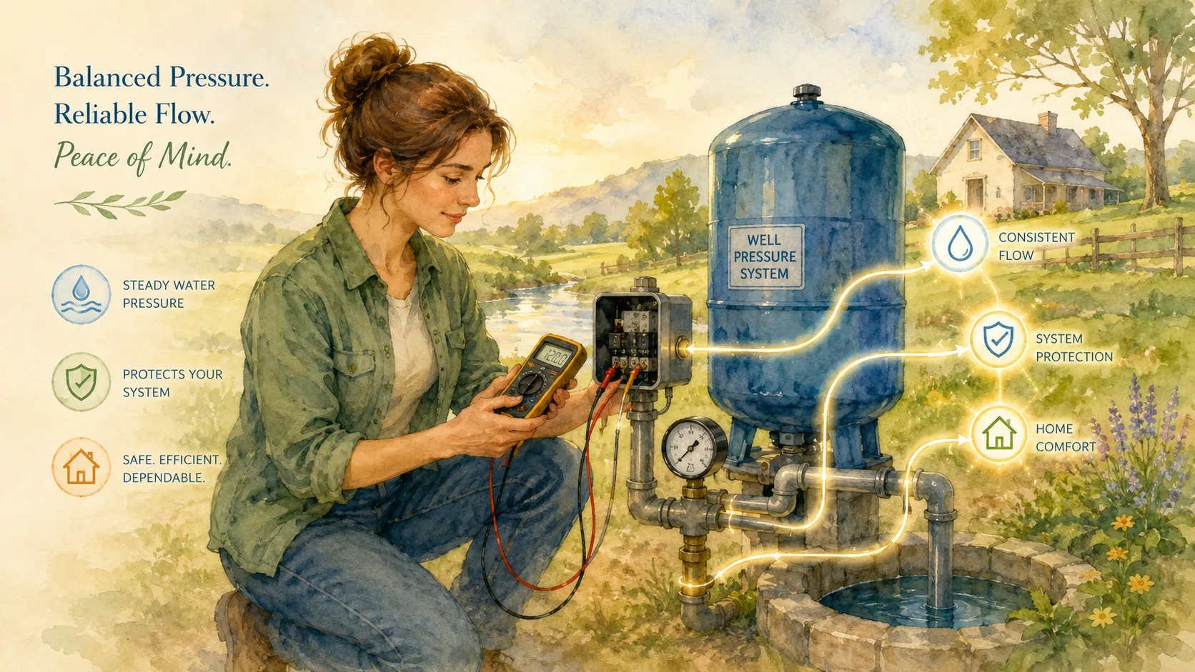
A private well system feels almost invisible when it works correctly. You turn on the faucet, water flows instantly, and life continues without a second thought. The moment the water pressure starts fluctuating or disappears entirely, though, that tiny pressure switch suddenly becomes one of the most important electrical components in your home. Many homeowners assume a failing well pump is always the problem, but real-world troubleshooting data shows that a worn or malfunctioning pressure switch is often the actual culprit. Recent well system service reports in 2026 indicate that pressure switches are among the most commonly replaced well components because contact wear, corrosion, sediment buildup, and electrical arcing gradually damage the switch over time.
Testing a well pressure switch with a multimeter is one of the fastest ways to determine whether the switch is functioning correctly or whether another issue is hiding deeper inside the system. The process sounds intimidating at first because it involves electricity, water pressure, and wiring terminals all packed into one small box. Still, once you understand the logic behind the switch, the testing process becomes surprisingly straightforward. Think of the pressure switch as a traffic controller standing between your well pump and your pressure tank. It constantly monitors pressure levels and decides when the pump should start or stop. If that controller stops doing its job, the entire system begins acting unpredictably.
This guide walks through every major step involved in diagnosing a well pressure switch safely and accurately using a multimeter. You will learn how the switch works, what warning signs usually appear before failure, how to check voltage and continuity, which pressure settings matter most, and when replacement makes more sense than adjustment. By the end, you will understand not only how to test the switch but also how to interpret what the readings actually mean in the real world.
Understanding the Role of a Well Pressure Switch
What a Well Pressure Switch Actually Controls
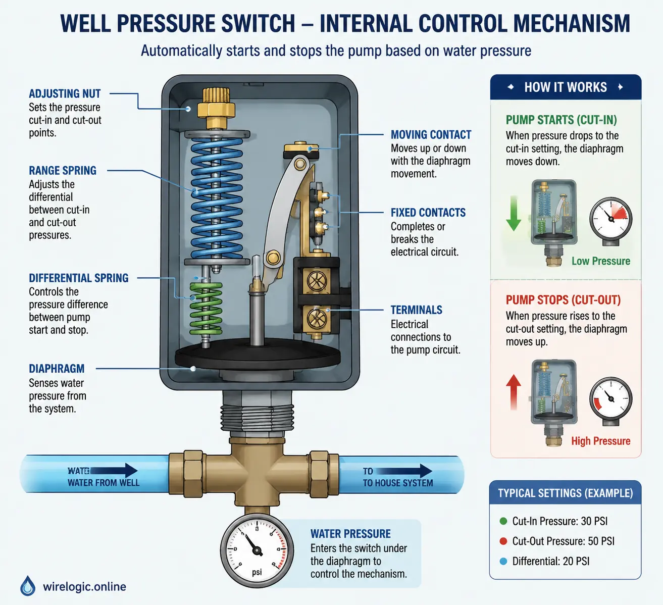
The well pressure switch acts as the command center for your entire water delivery system. Its main job is simple in theory: monitor water pressure inside the pressure tank and activate the well pump whenever pressure falls below a certain level. Once the system reaches the desired pressure again, the switch cuts power to the pump and stops it from running continuously. Most residential systems operate on either a 30/50 PSI setup or a 40/60 PSI setup. That means the pump starts at either 30 or 40 PSI and stops at either 50 or 60 PSI.
The switch performs this task using a spring-loaded mechanical mechanism attached to electrical contacts. As water pressure changes, the internal diaphragm inside the switch reacts to those changes. When pressure drops low enough, the contacts close and send electricity to the pump. When pressure rises to the cut-off point, the contacts open and shut the pump off. It sounds almost old-fashioned compared to modern digital electronics, but this mechanical simplicity is actually why well pressure switches remain widely used today.
Problems begin when the contacts inside the switch become pitted or burned from electrical arcing. Over time, repeated opening and closing creates tiny sparks that slowly damage the metal surfaces. Corrosion, moisture, insects, or sediment can also interfere with the mechanism. According to recent well service troubleshooting reports, pitted contacts and clogged sensing ports remain among the most common causes of switch failure.
Understanding this operating principle matters because your multimeter readings only make sense when you know what the switch should be doing under different pressure conditions. A switch that should be closed but reads open indicates one type of failure. A switch stuck closed when pressure is already high points to an entirely different issue. The multimeter becomes your translator, turning invisible electrical behavior into information you can actually use.
Why Pressure Settings Matter in Daily Water Use
Most homeowners never think about PSI settings until the shower suddenly loses pressure or the pump refuses to stop running. Yet those settings influence nearly every aspect of your daily water experience. A 30/50 system generally works well for smaller homes and shorter plumbing runs, while a 40/60 setup often delivers stronger pressure for larger homes or irrigation systems.
Pressure settings also directly affect the lifespan of your well equipment. If the cut-in and cut-out pressures are improperly adjusted, the pump may cycle too frequently. This condition, commonly called short cycling, rapidly wears down pump motors, pressure tanks, and switch contacts. Imagine starting your car engine every thirty seconds all day long. Eventually, something will fail from sheer repetition. That same principle applies to well pumps.
Tank air pressure plays a critical role as well. Industry guidance recommends setting tank pre-charge pressure approximately 2 PSI below the cut-in setting. A 30/50 system usually requires a 28 PSI tank charge, while a 40/60 system typically uses 38 PSI. If those numbers are mismatched, the switch may behave erratically even when the electrical components are technically functioning.
This is why pressure switch diagnosis cannot rely only on electrical testing. A perfectly good switch can appear faulty if the pressure tank is waterlogged or the system cannot build sufficient pressure. Successful troubleshooting always combines electrical readings with mechanical observations. The multimeter gives you one piece of the puzzle, but pressure behavior tells the rest of the story.
Common Symptoms of a Faulty Well Pressure Switch
Water Pressure Fluctuations and Short Cycling
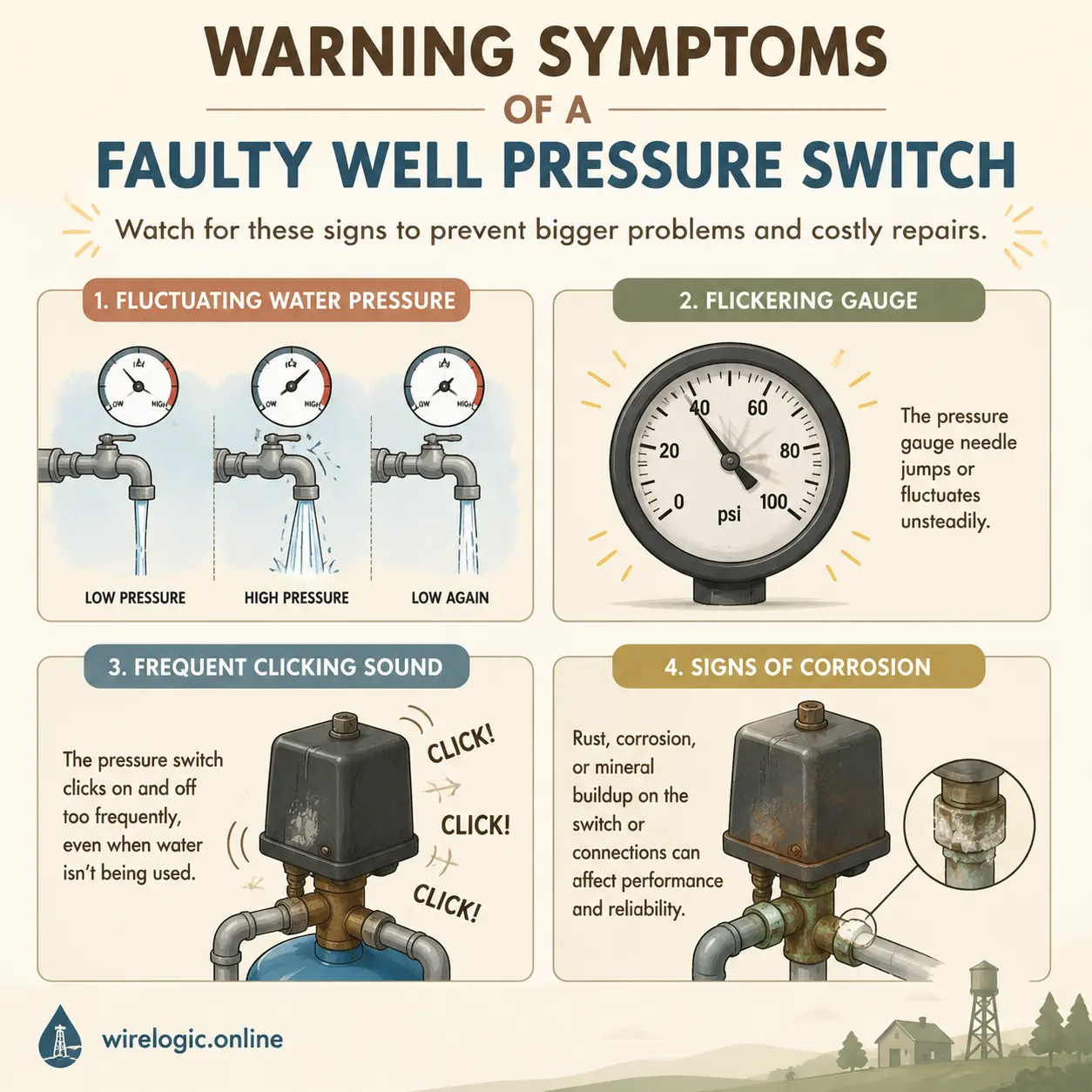
One of the earliest warning signs of pressure switch trouble is inconsistent water pressure throughout the home. Maybe the shower pressure suddenly surges and drops without warning, or perhaps the kitchen faucet pulses unpredictably. These symptoms often happen because the pressure switch contacts are failing to maintain consistent electrical continuity. Instead of cleanly opening and closing, the contacts begin chattering or sticking intermittently.
Short cycling is another classic symptom. In this situation, the well pump turns on and off repeatedly within very short intervals. You may hear rapid clicking sounds near the pressure tank, or notice the pump activating every few seconds while using water. Although a waterlogged pressure tank is frequently responsible for short cycling, worn pressure switch contacts can accelerate the problem dramatically.
The reason short cycling is dangerous comes down to heat and stress. Electric motors experience their highest electrical load during startup. Every additional cycle increases wear on the pump motor and creates more electrical arcing inside the switch itself. What starts as a minor annoyance can eventually destroy expensive system components if ignored for too long.
Sometimes homeowners misdiagnose these symptoms because they assume fluctuating pressure automatically means a failing pump. In reality, the pressure switch often serves as the weakest link in the chain. Replacing a $30 switch is far less painful than replacing a deep well pump buried hundreds of feet underground. That is exactly why proper multimeter testing matters before spending money on larger repairs.
Pump Running Constantly or Refusing to Start
A pump that never shuts off is one of the most alarming well system problems a homeowner can face. In some cases, the issue comes from the system being unable to reach cut-off pressure due to leaks, clogged pipes, or a failing pump. But stuck pressure switch contacts are also a major cause. Electrical arcing can literally weld the contacts together over time, forcing the pump to run continuously.
On the opposite end of the spectrum, the pump may refuse to start entirely. You open a faucet and nothing happens. No water. No pressure. Maybe you hear a faint clicking sound, but the pump never activates. This situation commonly points toward burned or corroded contacts preventing electricity from reaching the pump motor. Sometimes the contacts physically move but fail to conduct electricity effectively because the metal surfaces are too damaged.
A multimeter becomes incredibly valuable here because voltage testing immediately reveals whether power is reaching the switch and whether the switch is successfully passing that voltage onward to the pump. Without testing, homeowners often resort to guesswork. Guesswork with electrical systems rarely ends well.
Burning Smells, Clicking Sounds, and Visible Corrosion
Pressure switches often provide visual clues before they fail completely. Burn marks around the terminals, melted insulation, rust buildup, or heavy corrosion all indicate electrical stress or moisture intrusion. According to recent field reports from well technicians, loose wire connections remain one of the most common causes of overheating and arcing inside switch housings.
Clicking noises can also reveal important information. A healthy switch normally clicks once when pressure drops and once again when pressure rises to the cut-off level. Repeated rapid clicking or buzzing usually signals unstable contacts or insufficient voltage. Think of it like a light switch flickering repeatedly instead of turning fully on or off. The mechanism is trying to work but failing to complete the action cleanly.
Moisture is another silent enemy. Many pressure switches are installed in damp basements, crawl spaces, or pump houses where humidity and condensation gradually corrode metal components. Even insects can interfere with operation. Some technicians report ant infestations inside pressure switches because the warmth and electrical fields attract them.
When visual symptoms appear alongside water pressure problems, multimeter testing should happen immediately before more expensive components become damaged.
Safety Precautions Before Testing the Pressure Switch
Turning Off Electrical Power Properly
Before touching any well pressure switch, electrical safety must come first. Most residential well systems operate on 240 volts, which is powerful enough to cause serious injury or death. Turning off the breaker is mandatory before removing the switch cover or touching any wiring. Recent safety guidance from well service professionals repeatedly emphasizes verifying power shutdown with a voltage tester rather than trusting the breaker label alone.
Many homeowners underestimate this risk because the pressure switch looks small and harmless. The reality is that it directly controls a high-voltage pump circuit. Treating it casually is like assuming a small snake cannot bite because it is short. Size has nothing to do with danger.
After shutting off the breaker, use your multimeter to confirm there is no live voltage at the line terminals. Only then should you proceed with visual inspection or continuity testing. Wearing insulated gloves and keeping the area dry also adds an extra layer of protection. Water and electricity make a terrible combination, especially around exposed terminals.
Tools Needed for Safe Multimeter Testing
Testing a well pressure switch does not require a massive toolbox, but using the right tools makes the process safer and more accurate. At minimum, you should have:
| Tool | Purpose |
|---|---|
| Digital multimeter | Measure voltage and continuity |
| Insulated screwdriver | Remove switch cover safely |
| Flashlight | Improve visibility in dark pump areas |
| Needle-nose pliers | Handle wires carefully |
| Safety gloves | Reduce electrical risk |
A quality digital multimeter is the centerpiece of the entire diagnosis process. Voltage mode helps confirm whether electricity is reaching and leaving the switch, while continuity mode verifies whether the contacts open and close correctly. Some homeowners attempt to troubleshoot without a meter, relying only on visual inspection. That approach is like diagnosing engine trouble without ever opening the hood.
How to Test a Well Pressure Switch with a Multimeter
Checking for Incoming Voltage at the Switch
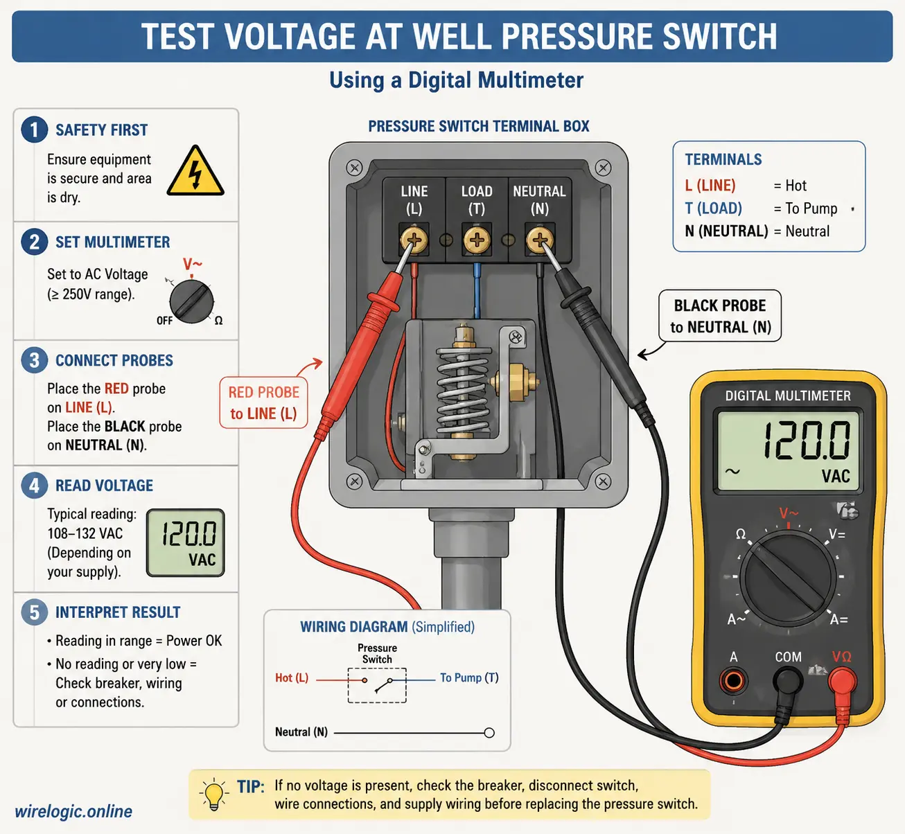
The first electrical test involves verifying incoming voltage. Restore power temporarily after removing the switch cover safely. Set the multimeter to AC voltage mode and carefully place the probes across the line terminals feeding the switch. Most residential systems should read approximately 240 volts across the two hot wires. Some systems may show around 120 volts from each hot wire to ground individually.
If no voltage appears at the line side, the problem likely exists upstream. A tripped breaker, failed breaker, damaged wiring, or disconnected conduit may be responsible. Recent troubleshooting discussions show that homeowners sometimes measure 120 volts on each leg individually but still fail to get 240 volts across both terminals because of a faulty breaker connection.
This test establishes whether power is even available to the pressure switch. Without incoming voltage, the switch itself cannot function regardless of its condition.
Testing Voltage Across Load Terminals
Once incoming power is confirmed, the next step is checking the load side of the switch; the terminals leading toward the well pump. When system pressure is below cut-in PSI, the switch contacts should close and send voltage to the pump. Your multimeter should show approximately 240 volts across the load terminals during this condition.
If voltage exists on the line side but not on the load side while pressure is low, the contacts may be burned, stuck open, or failing internally. This is one of the clearest indicators of a defective pressure switch. On the other hand, if voltage successfully leaves the switch but the pump still refuses to operate, the issue may lie deeper in the wiring or within the pump itself.
Voltage drop behavior can also reveal hidden wiring faults. Some technicians report seeing voltage collapse dramatically when the pump attempts to start, indicating damaged wires or failing motors creating excessive load.
Continuity Testing to Verify Contact Operation
Continuity testing works best with power turned completely off again. Set the multimeter to continuity or resistance mode. Place probes on the switch terminals and observe whether the circuit opens and closes properly as pressure changes.
When pressure is below cut-in level, the contacts should close and continuity should exist. When pressure rises above cut-out level, the contacts should open and continuity should disappear.
A switch stuck permanently open or permanently closed indicates mechanical failure. Burned contacts may also produce inconsistent readings that fluctuate unpredictably. This is where experience becomes valuable because intermittent failures sometimes appear normal during quick testing sessions. If readings jump around erratically, contact wear is often responsible.
Understanding Multimeter Readings Correctly
Reading the multimeter correctly matters just as much as performing the test itself. A common mistake is assuming any voltage reading means the switch is healthy. In reality, the critical factor is whether the switch changes state appropriately when pressure changes.
For example:
| Condition | Expected Result |
|---|---|
| Pressure below cut-in | Contacts closed, continuity present |
| Pressure above cut-out | Contacts open, continuity absent |
| Incoming power test | Around 240V AC |
| Outgoing power during pump activation | Around 240V AC |
Consistent readings that match pressure behavior usually indicate a healthy switch. Readings that contradict expected operation point toward failure.
Pressure Settings That Affect Switch Operation
Understanding 30/50 and 40/60 Pressure Settings
The majority of residential well systems use either 30/50 or 40/60 pressure settings. These numbers represent cut-in and cut-out pressures respectively.
<math xmlns="
Higher pressure settings generally provide stronger water flow but place more stress on pumps and plumbing components. Improper adjustments can create system instability, especially if the pressure tank charge does not match the switch configuration.
Homeowners sometimes attempt random adjustments hoping to improve water pressure, but changing the spring tension blindly can create more problems than it solves. Think of it like adjusting your car brakes without understanding hydraulics. A small change can dramatically affect system behavior.
Tank Air Pressure and Its Connection to Switch Performance
Pressure tanks and pressure switches operate as partners. If the tank loses air charge or becomes waterlogged, the switch experiences rapid cycling and increased wear. Current guidance recommends setting tank pressure 2 PSI below the cut-in pressure.
<math xmlns="
This small detail has enormous consequences for system stability. Incorrect tank pressure can mimic pressure switch failure even when the electrical components remain functional.
Common Wiring Problems in Well Pressure Systems
Loose Terminals and Damaged Insulation
Loose wiring creates resistance, heat, and arcing inside the switch housing. Over time, terminals loosen naturally from vibration and repeated thermal expansion. Reddit troubleshooting discussions in 2026 highlighted several cases where poorly secured wires caused overheating and intermittent operation.
Damaged insulation creates another major hazard. Exposed conductors can short against metal housings or each other, creating fire risk and unreliable operation. Wiring problems often mimic switch failure, which is why careful inspection always matters before replacing parts unnecessarily.
Voltage Drops and Breaker Issues
Voltage drop problems can confuse even experienced homeowners. A multimeter may show correct voltage with no load attached, only for voltage to collapse when the pump attempts to start. This situation often points toward failing motors, damaged underground wires, or bad breakers.
The pressure switch sometimes gets blamed unfairly because it happens to sit at the center of the system. Effective troubleshooting means following the electrical path logically instead of replacing random components.
Repair or Replace? Making the Right Decision
When Cleaning or Adjustment Is Enough
Not every pressure switch problem requires full replacement. Minor corrosion, insect contamination, or light sediment buildup can sometimes be cleaned carefully. Slight pressure adjustments may also restore proper operation if settings drifted over time.
Lightly pitted contacts occasionally respond to gentle cleaning, though heavily burned contacts rarely remain reliable for long. If the switch still responds consistently after cleaning and testing, replacement may not be immediately necessary.
Knowing When the Switch Must Be Replaced
Some symptoms clearly indicate replacement is the smarter choice. Severe contact burning, melted insulation, cracked housings, stuck contacts, or persistent inconsistent readings usually justify installing a new switch. Fortunately, pressure switches remain relatively inexpensive compared to pumps or tanks. Recent estimates place replacement switch costs between $20 and $75 for most residential systems.
If the switch has already begun overheating or arcing heavily, replacement should happen immediately. Electrical fires and pump damage are not worth gambling over a low-cost component.
Conclusion
Testing a well pressure switch with a multimeter is one of the most practical diagnostic skills a homeowner can learn. The process combines electrical testing, mechanical observation, and pressure system understanding into a straightforward troubleshooting method that can save significant time and money. Instead of automatically assuming the well pump has failed, proper voltage and continuity testing helps isolate the real issue accurately.
A healthy pressure switch should receive incoming voltage, pass power correctly to the pump, and open or close its contacts consistently according to system pressure. When the switch begins showing signs of corrosion, erratic cycling, voltage loss, or burned contacts, the warning signs should never be ignored. Catching these issues early prevents larger failures and protects the entire well system from unnecessary wear.
The most important takeaway is that well pressure systems operate as connected systems rather than isolated parts. The switch, pressure tank, wiring, breaker, and pump all influence one another. Effective troubleshooting means understanding how those pieces interact instead of focusing on only one component. Once you combine multimeter testing with pressure behavior observations, diagnosing well pressure switch problems becomes far less mysterious and much more manageable.
FAQs
1. What voltage should a well pressure switch have?
Most residential well pressure switches operate on approximately 240 volts AC. You should typically measure around 240V across the line terminals when testing with a multimeter.
2. Can a pressure switch fail intermittently?
Yes. Pressure switch contacts can become pitted or corroded over time, causing inconsistent operation. Intermittent clicking, fluctuating pressure, or random pump shutdowns are common symptoms.
3. How do I know if my well pump or pressure switch is bad?
If voltage enters the pressure switch but does not leave through the load terminals when pressure is low, the switch is likely faulty. If voltage leaves the switch correctly but the pump still does not run, the pump or wiring may be the problem.
4. Should I clean or replace a corroded pressure switch?
Minor corrosion may be cleaned carefully, but heavily burned or pitted contacts usually require replacement. Persistent overheating or arcing should never be ignored.
5. What pressure setting is best for residential wells?
Most homes use either 30/50 PSI or 40/60 PSI settings. Smaller homes often work well with 30/50 systems, while larger homes may benefit from the stronger pressure provided by 40/60 systems.

Colt Marlowe is a 29-year-old American content writer based in Boise, Idaho. He specializes in technology, digital tools, and online business topics, combining years of research with practical experience to produce clear, trustworthy articles. As a contributor to wirelogic.online, he focuses on creating well-researched, reader-friendly content that emphasizes accuracy, transparency, and long-term value for audiences seeking reliable information.