
Installing a 125 amp sub panel sounds straightforward at first. You buy the panel, run the wire, connect the breaker, and power flows where you need it. But the moment you start researching wire size, the answers seem to scatter in every direction. One electrician says use #1 copper. Another recommends 1/0 aluminum. Someone online insists #2 copper is enough, while another warns that undersized wire could become a fire hazard. Suddenly, what looked like a simple project starts feeling like a maze of confusing electrical jargon.
The truth is that wire sizing for a 125 amp sub panel is not based on a single magic number. Several important factors shape the final decision, including conductor material, distance, voltage drop, ambient temperature, conduit fill, and National Electrical Code requirements. A feeder wire that works perfectly in one installation might be unsafe in another. That’s why professional electricians don’t guess. They calculate.
According to updated NEC-based wire sizing references published in 2026, the most commonly accepted minimum feeder sizes for a 125 amp subpanel are 1 AWG copper or 2/0 AWG aluminum conductors under standard 75°C conditions. These recommendations align with modern electrical code ampacity tables and account for typical residential feeder installations. Still, those numbers are only the starting point, not the whole story.
This guide breaks down every critical factor that affects wire sizing for a 125 amp sub panel. You’ll learn how ampacity works, why voltage drop matters, how copper compares with aluminum, what grounding rules apply, and which common mistakes often lead to overheating problems. By the end, you’ll understand not only which wire size is commonly used, but why that size matters so much for safety, efficiency, and long-term reliability.
Why Wire Size Matters for a 125 Amp Sub Panel
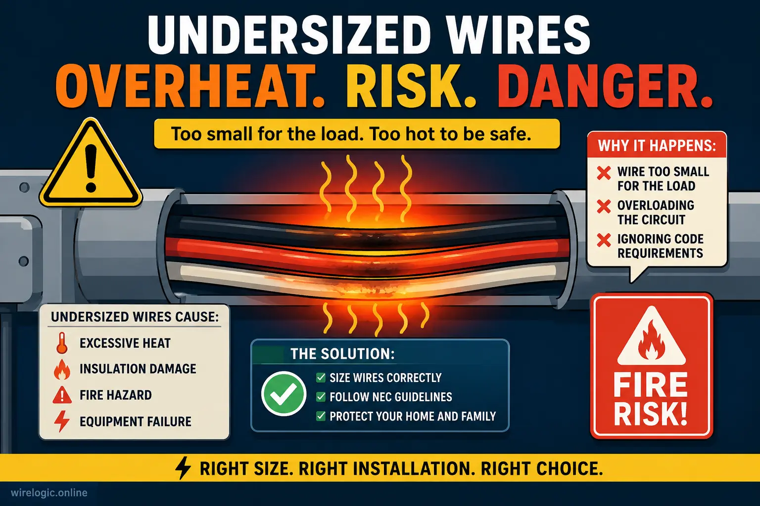
Choosing the correct wire size for a high-amperage feeder is a lot like choosing the right-sized arteries for the human body. If the pathway is too narrow, resistance builds up, heat increases, and the entire system struggles under pressure. Electrical conductors behave in a very similar way. When wires are too small for the current flowing through them, they overheat, insulation degrades, and equipment performance suffers. In extreme cases, undersized wiring becomes a serious fire hazard.
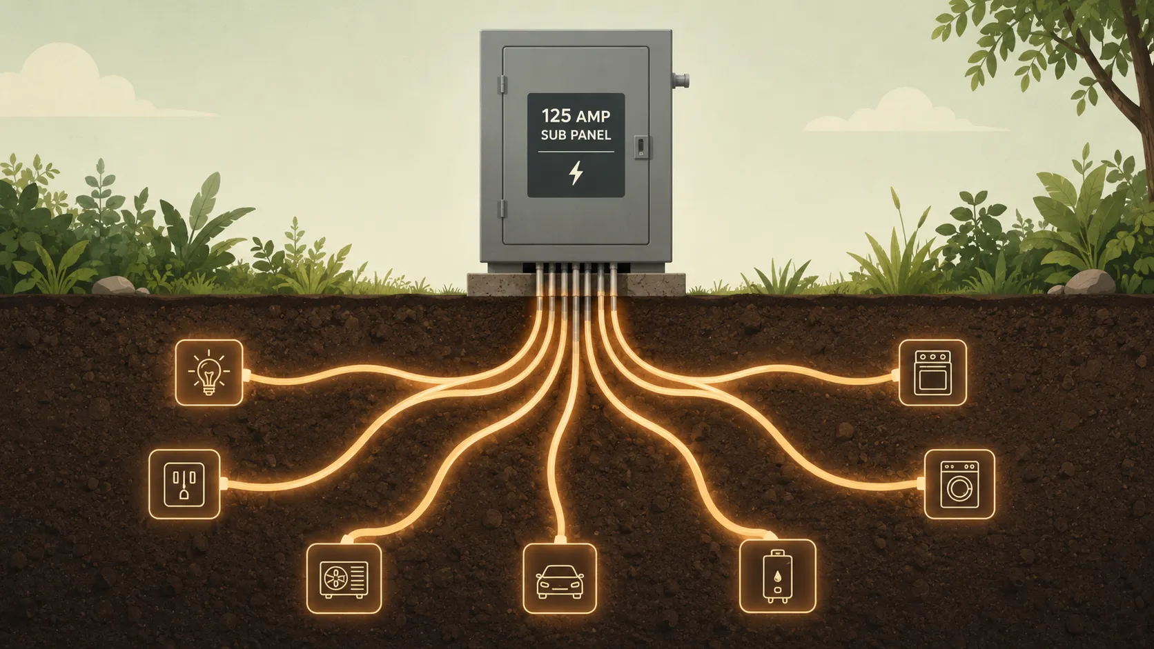
A 125 amp sub panel is typically installed to power major electrical loads such as workshops, detached garages, accessory dwelling units, HVAC equipment, or expanded living spaces. These applications often involve continuous heavy loads that place significant stress on feeder conductors. That’s why proper ampacity becomes essential. Ampacity refers to the maximum amount of current a wire can safely carry without exceeding its temperature rating. If the wire cannot handle the load continuously, dangerous heat buildup begins inside the conductor.
The Safety Risks of Undersized Conductors
One of the biggest problems with undersized feeder wiring is that overheating often happens silently. The breaker may not trip immediately because breakers are designed to protect against overcurrent, not gradual thermal damage caused by resistance. Meanwhile, the wire insulation slowly deteriorates over time. This hidden degradation can lead to arcing, melted insulation, damaged terminals, or electrical fires inside walls and conduit systems.
Electricians frequently warn homeowners about relying on internet shortcuts when sizing subpanel feeders. Discussions among licensed electricians repeatedly emphasize that many people confuse service conductor rules with feeder conductor rules, leading to dangerously undersized installations. A common mistake involves assuming that a wire barely matching the breaker rating under ideal conditions will remain safe in every installation environment. Real-world conditions are rarely ideal.
How Ampacity Determines Electrical Performance
Ampacity tables published in NEC references are based on variables like conductor material, insulation temperature rating, ambient heat, and installation method. For example, 1 AWG copper conductors commonly provide enough ampacity for a 125 amp feeder under 75°C termination ratings, while aluminum conductors typically require 2/0 AWG because aluminum has lower conductivity than copper.
Performance matters just as much as safety. Improperly sized conductors create voltage instability, especially when motors or compressors start under load. You may notice dimming lights, sluggish equipment startup, or shortened appliance lifespan. In a workshop, that could mean power tools struggling under load. In an HVAC system, it could mean compressors overheating prematurely. Proper wire sizing keeps electrical systems stable and efficient, even during peak demand.
Standard Wire Sizes for a 125 Amp Sub Panel
The question most people ask first is simple: what wire size should be used for a 125 amp sub panel? Under standard residential installation conditions, the commonly recommended minimum conductor sizes are:
| Conductor Material | Common Minimum Size | Typical Ampacity |
|---|---|---|
| Copper | 1 AWG | Around 130A |
| Aluminum | 2/0 AWG | Around 135A |
These recommendations come from modern NEC ampacity references and feeder sizing guides updated for 2026 installations.
Recommended Copper Wire Sizes
Copper remains the gold standard for electrical conductors because of its excellent conductivity, strength, and durability. A 1 AWG copper conductor is commonly selected for 125 amp subpanels because it safely supports the feeder load under standard 75°C termination conditions. Copper also handles heat better than aluminum and experiences less thermal expansion over time.
One advantage of copper is that it allows smaller conductor sizes while maintaining equivalent ampacity. That makes conduit installations easier, especially in tight bends or crowded raceways. Copper also resists corrosion more effectively and generally provides more reliable terminal connections over long periods. These advantages explain why many electricians still prefer copper despite its significantly higher cost.
The downside is price. Copper prices remain substantially higher than aluminum, particularly for long feeder runs. On a short installation, the difference may not matter much. On a 150-foot underground feeder, however, copper costs can quickly become significant enough to push homeowners toward aluminum alternatives.
Recommended Aluminum Wire Sizes
Aluminum conductors require larger sizes because aluminum carries electricity less efficiently than copper. Most modern guides recommend 2/0 aluminum conductors for 125 amp feeders. While older installations sometimes used smaller aluminum sizes, current code-compliant practices typically favor the larger 2/0 size for safety and voltage drop performance.
Despite its larger diameter, aluminum remains extremely popular for subpanel feeders because it costs dramatically less than copper. Industry comparisons published in 2026 estimate aluminum conductors cost approximately 40–60% less per amp-foot than copper. For detached garages, workshops, or accessory dwelling units requiring long underground runs, those savings can become substantial.
Modern aluminum alloys are also much safer than older aluminum branch-circuit wiring from decades ago. Today’s aluminum feeder conductors are engineered specifically for high-amperage applications and perform very well when installed correctly using anti-oxidant compounds and properly rated lugs.
Factors That Determine Wire Size for a 125 Amp Sub Panel
A 125 amp breaker alone does not automatically dictate the wire size. That surprises many homeowners because they assume breaker size and conductor size always match directly. In reality, electrical systems behave more like ecosystems than simple plug-and-play components. Every installation has unique conditions that influence how much heat the conductor generates and how efficiently it can dissipate that heat.
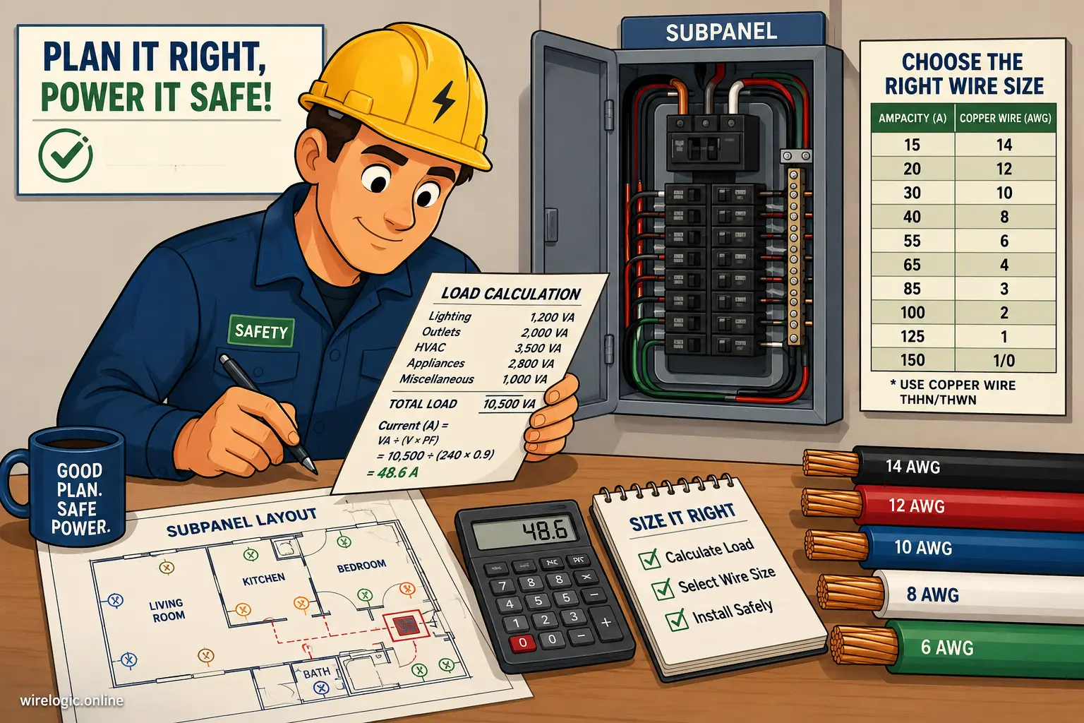
Load Calculation Requirements
Before sizing conductors, electricians perform a load calculation to determine the expected demand on the subpanel. NEC load calculations consider appliances, HVAC systems, lighting, receptacles, cooking equipment, and continuous loads. A detached garage with basic lighting and occasional tool usage may never approach 125 amps in actual demand. Meanwhile, an accessory dwelling unit with electric cooking, HVAC, laundry equipment, and water heating could place sustained heavy demand on the feeder.
Experienced electricians repeatedly emphasize that the subpanel rating itself does not determine actual feeder load requirements. Installing a 125 amp panel does not necessarily mean the feeder will continuously carry 125 amps. Still, feeder conductors must be capable of safely handling the breaker protection and anticipated load conditions.
Continuous loads are especially important. NEC rules generally require continuous loads to be calculated at 125% of their actual running current. That additional buffer helps prevent long-term overheating during sustained operation.
Ambient Temperature and Installation Conditions
Wire ampacity changes dramatically depending on installation conditions. Conductors installed inside hot attics, crowded conduits, or outdoor raceways exposed to sunlight may require derating adjustments. Heat is the enemy of conductor performance. When surrounding temperatures rise, wires lose some of their ability to dissipate internally generated heat.
Conduit fill also matters. Multiple current-carrying conductors packed tightly together create mutual heating effects. Imagine several space heaters operating inside a narrow pipe. Heat accumulates quickly because airflow is restricted. Electrical conductors behave similarly inside overloaded conduit systems.
Insulation ratings further complicate sizing decisions. Conductors with 90°C insulation may still be limited by 75°C terminal ratings at breakers and panels. That’s one reason many electricians size conservatively, often choosing the next larger conductor size to create extra safety margin.
Copper vs Aluminum Conductors for High Amperage Loads
The debate between copper and aluminum conductors has existed for decades, and both materials have loyal supporters. Choosing between them often comes down to balancing budget, installation complexity, conductivity, and long-term maintenance expectations.
Cost Differences Between Copper and Aluminum
Copper delivers excellent performance, but it comes with a premium price tag. For shorter feeder runs, the cost difference might seem manageable. Once distances increase, however, material expenses climb rapidly. Aluminum becomes extremely attractive for long underground feeders because it offers major cost savings without sacrificing acceptable performance.
Modern electrical industry comparisons show aluminum feeders often reduce material costs by nearly half compared with copper. On a long feeder run to a detached structure, that difference can easily amount to hundreds or even thousands of dollars.
The tradeoff is conductor size. Because aluminum is less conductive, installers must use larger gauges to achieve equivalent ampacity. Larger conductors require larger conduit sizes and sometimes create more difficult pulling conditions during installation.
Conductivity and Durability Comparison
Copper remains superior in conductivity, tensile strength, and resistance to expansion and contraction. It forms tighter, more reliable connections and generally requires less maintenance over time. That’s one reason many electricians still prefer copper for premium residential installations.
Aluminum, meanwhile, expands and contracts more significantly during heating cycles. If terminals are improperly torqued or anti-oxidant compounds are omitted, loose connections may develop over time. Loose electrical connections create resistance, resistance creates heat, and heat creates failure points.
Still, properly installed aluminum feeders perform extremely well in modern high-amperage applications. Large commercial feeders and utility distribution systems rely heavily on aluminum conductors every day. The key is proper installation technique, correct lug compatibility, and adherence to code-approved connection methods.
Distance and Voltage Drop Considerations
Distance changes everything in electrical systems. A wire that performs perfectly over a 30-foot run may become completely inadequate at 200 feet. That’s because voltage naturally drops as current travels through conductors. The longer the distance, the greater the resistance and resulting voltage loss.
Why Long Wire Runs Require Larger Conductors
Voltage drop is similar to water pressure loss in a long garden hose. The farther the water travels, the weaker the pressure becomes at the far end. Electrical current experiences a comparable effect. Excessive voltage drop causes equipment inefficiency, overheating, dimming lights, and motor startup problems.
Modern NEC guidance recommends limiting branch circuit voltage drop to approximately 3%, with total feeder and branch voltage drop staying under 5%. For a 125 amp subpanel located far from the main service, this often means upsizing conductors beyond minimum ampacity requirements.
Recent 2026 wire sizing references show that a standard 1 AWG copper feeder may maintain acceptable voltage drop for roughly 187 feet on a 240V system before exceeding recommended limits. Beyond that distance, electricians commonly increase conductor size to 1/0 or 2/0 copper.
Recommended Voltage Drop Limits
Voltage drop calculations become especially important in detached structures like workshops and garages where motors, compressors, welders, or HVAC systems operate. Motors are particularly sensitive to low voltage conditions because they draw additional current while struggling to start or maintain torque.
Here’s a simplified comparison of how distance influences conductor selection:
| Distance | Common Copper Recommendation | Common Aluminum Recommendation |
|---|---|---|
| Under 100 ft | 1 AWG | 2/0 AWG |
| 100–175 ft | 1/0 AWG | 3/0 AWG |
| Over 175 ft | 2/0 AWG | 4/0 AWG |
These are generalized examples only. Actual sizing depends on calculated load, voltage, conductor type, and installation conditions.
Ground and Neutral Requirements for Subpanel Wiring
Subpanel grounding rules create confusion for many DIY installers because subpanels are wired differently than main service panels. Understanding the distinction between neutral and grounding conductors is critical for safety.
Separating Grounds and Neutrals
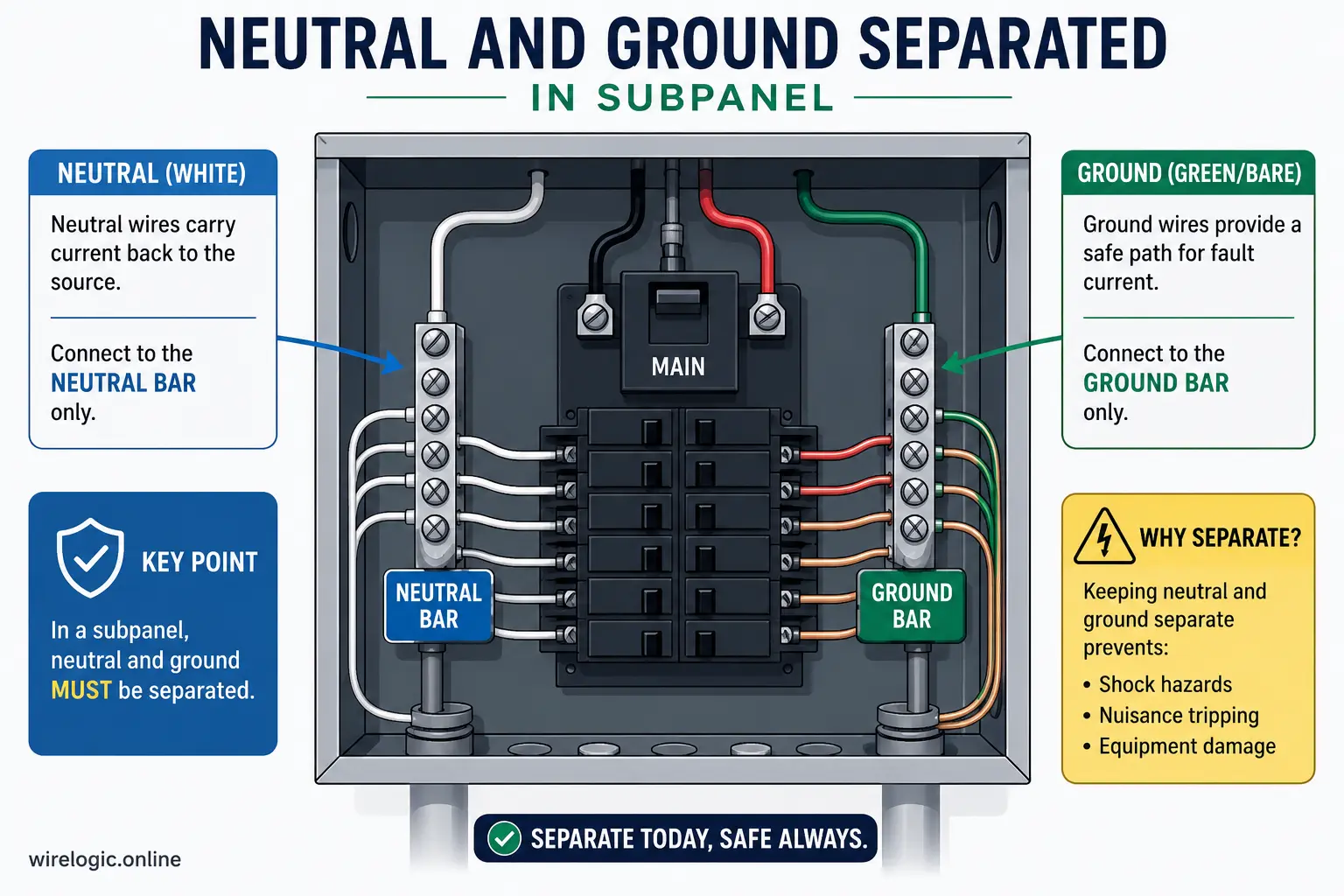
In a main service panel, neutrals and grounds are bonded together. In a subpanel, they must remain isolated. That means the neutral bus and ground bus cannot be electrically connected inside the subpanel enclosure. The grounding conductor provides a fault-return path for safety, while the neutral carries return current during normal operation.
Failing to separate grounds and neutrals in a subpanel can energize metal enclosures and create dangerous shock hazards. Detached structures may also require grounding electrode systems, including ground rods, depending on installation conditions and local code requirements. NEC references for feeder installations specifically address these grounding requirements under sections related to subpanels and detached structures.
Ground Wire Sizing Guidelines
Grounding conductors are sized differently than feeder conductors. Their size depends primarily on the rating of the overcurrent protection device rather than the ampacity of the feeder itself. For a typical 125 amp feeder, many installations use 6 AWG copper grounding conductors or equivalent aluminum sizes. Electrician discussions frequently reference NEC grounding tables supporting these common grounding conductor sizes.
The grounding conductor must also be compatible with the installation environment. Outdoor and underground installations often require corrosion-resistant materials and approved burial methods.
Conduit Fill and Installation Conditions That Matter
Electrical conduit is not just a protective tube. It directly affects conductor temperature, pulling tension, airflow, and long-term reliability. Improper conduit sizing creates installation headaches and increases overheating risks.
Conduit Sizing and Heat Dissipation
Large feeder conductors occupy significant conduit space, especially aluminum conductors. NEC conduit fill limits help maintain adequate airflow and pulling clearance. Overfilled conduit traps heat and increases friction during installation. Excessive pulling force can damage insulation and weaken conductors before the system is ever energized.
For example, many 125 amp aluminum feeder installations use 1-1/4 inch PVC conduit for underground runs. Larger conduit may be necessary if additional conductors or future expansion circuits are included.
Conduit material also matters. PVC conduit performs well underground and resists corrosion, while metal conduit may provide additional physical protection in exposed areas. Temperature conditions differ depending on conduit placement, sunlight exposure, and burial depth.
Indoor vs Outdoor Installation Requirements
Indoor feeders usually experience more stable environmental conditions than outdoor feeders. Outdoor conduit exposed to direct sunlight may reach extremely high temperatures during summer months, reducing conductor ampacity. Underground conduit introduces different concerns, including moisture resistance and thermal dissipation through soil.
Installers must also select conductors approved for the installation environment. THWN-2 conductors are commonly used because they are rated for wet locations and higher temperature performance. Incorrect conductor selection can violate code and shorten system lifespan dramatically.
Common Sizing Mistakes That Lead to Overheating
Most feeder failures do not happen because people intentionally ignore safety rules. They happen because electrical code details are misunderstood or oversimplified. Small calculation mistakes often snowball into serious long-term problems.
Using the Wrong Ampacity Column
One of the most common errors involves using the wrong temperature column from NEC ampacity tables. Conductors may carry a 90°C insulation rating, but breaker and panel terminations are frequently limited to 75°C. That lower termination rating controls the allowable ampacity in many installations.
Electricians discussing feeder sizing online regularly point out this exact mistake when homeowners attempt to justify smaller wire sizes. A wire appearing acceptable under the 90°C column may actually violate code once terminal limitations are considered.
Ignoring Continuous Loads and Future Expansion
Another major mistake is designing the feeder only for today’s load without considering future expansion. A garage initially used for lighting and small tools may later include EV chargers, compressors, welders, or HVAC systems. Suddenly, a once-adequate feeder becomes undersized.
Continuous loads create additional stress because the conductors operate near maximum capacity for extended periods. Heat accumulates gradually, especially in enclosed conduit systems. Conservative sizing provides valuable flexibility for future electrical demand growth.
Electrical Code Principles Related to Subpanel Feeders
The National Electrical Code serves as the backbone of safe electrical installation practices in the United States. While local jurisdictions may adopt slightly modified versions, NEC principles heavily influence nearly all residential feeder installations.
NEC Standards That Apply to 125 Amp Feeders
Several NEC sections commonly apply to subpanel feeder installations, including:
| NEC Area | Purpose |
|---|---|
| NEC 215.2 | Feeder conductor sizing |
| NEC 225.39 | Outdoor feeder and disconnect rules |
| NEC 250.32 | Grounding requirements for detached structures |
| NEC Table 310.16 | Conductor ampacity ratings |
| NEC Chapter 9 Table 8 | Voltage drop calculations |
These code principles exist because electrical systems must remain safe under real-world operating conditions, not just laboratory assumptions. Professional electricians often size conductors conservatively because installation variables like temperature, conduit fill, continuous load operation, and future expansion create uncertainty.
Electrical code is not merely bureaucratic paperwork. It represents decades of lessons learned from real electrical failures, fires, and equipment damage. Following those principles helps ensure that a 125 amp subpanel performs safely for decades rather than becoming a hidden hazard inside walls or underground conduit systems.
Conclusion
Choosing the correct wire size for a 125 amp sub panel involves much more than matching a breaker to a conductor. Wire material, distance, voltage drop, conduit fill, ambient temperature, grounding methods, and NEC ampacity rules all influence the final decision. Under standard residential conditions, 1 AWG copper and 2/0 aluminum conductors remain the most commonly recommended minimum feeder sizes for 125 amp subpanels.
Copper provides superior conductivity and durability, while aluminum offers major cost savings for long feeder runs. Voltage drop considerations may require upsizing conductors beyond minimum ampacity requirements, especially for detached garages, workshops, or accessory dwelling units located far from the main service panel.
Grounding and neutral separation rules are equally important. A properly wired subpanel isolates neutral and ground conductors while maintaining safe fault-current pathways through correctly sized grounding conductors. Installation conditions, including conduit fill and environmental heat exposure, also play major roles in long-term system reliability.
The safest approach is always to base feeder sizing on actual load calculations, NEC requirements, and the realities of the installation environment rather than internet shortcuts or guesswork. Electrical systems are unforgiving when improperly designed. Investing in correctly sized conductors today helps prevent overheating, equipment damage, nuisance voltage problems, and potentially catastrophic failures later.
FAQs
What is the minimum copper wire size for a 125 amp sub panel?
The most commonly recommended minimum size is 1 AWG copper under standard 75°C termination conditions.
What size aluminum wire is typically used for a 125 amp feeder?
Most modern NEC-based guides recommend 2/0 AWG aluminum conductors for a 125 amp subpanel feeder.
Does distance affect wire size for a subpanel?
Yes. Longer wire runs increase voltage drop, which often requires larger conductors to maintain safe and efficient electrical performance.
Can I use the same neutral and ground bar in a subpanel?
No. In a subpanel, the neutral and grounding conductors must remain isolated from each other to prevent dangerous fault-current conditions.
Is aluminum wire safe for a 125 amp subpanel?
Yes. Modern aluminum feeder conductors are widely used and considered safe when properly installed with approved connectors, anti-oxidant compounds, and correct torque specifications.