

Three phase power can look intimidating the first time you open an industrial electrical panel and see multiple energized conductors humming with energy. Unlike standard household single-phase electricity, three phase power systems distribute electricity using three alternating currents that operate slightly out of sync with each other. This design allows electrical equipment to run more smoothly, efficiently, and reliably, especially in factories, workshops, commercial buildings, and large HVAC systems. If you have ever wondered why industrial motors can run continuously for years without struggling like smaller household motors, three phase electricity is a major reason.
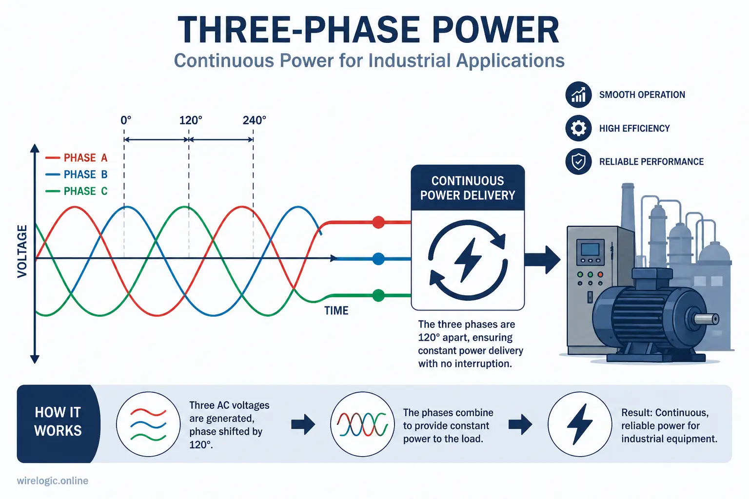
In a typical three phase system, you will encounter three hot wires commonly labeled L1, L2, and L3. These conductors carry alternating current that peaks at different times, creating a constant flow of usable power. That continuous energy delivery reduces vibration in motors and minimizes energy losses. It is almost like comparing a bicycle with one pedal to a machine powered by three synchronized engines. The motion becomes smoother and more stable because the power never completely drops off.
Three phase systems are commonly used in manufacturing plants, data centers, water treatment facilities, elevators, refrigeration systems, and heavy industrial machinery. Many commercial buildings also depend on three phase electricity because it can support large electrical loads more efficiently than single-phase systems. Understanding these fundamentals matters before attempting voltage testing because each measurement tells a story about how healthy or unhealthy the system may be.
When testing voltage on a three phase circuit, you are not simply checking whether power exists. You are diagnosing the condition of the entire electrical network. Balanced voltage readings usually indicate a healthy system, while inconsistent readings can signal overloaded circuits, failing transformers, loose terminals, or even dangerous wiring faults. A technician who understands the basics of three phase power is far more likely to identify issues before they become catastrophic failures.
What Makes Three Phase Electricity Different
The biggest difference between single-phase and three phase electricity lies in how power is delivered. In a single-phase system, power rises and falls in a wave pattern. In a three phase setup, three separate waveforms overlap, ensuring a nearly constant power supply. That means motors operate more efficiently and experience less stress during startup and operation.
y=sin(x)+sin(x+32π)+sin(x+34π)
.graphable-function-chartjs {
position: relative;
overflow: hidden;
touch-action: none;
}
.graphable-function-chartjs-tooltip {
position: absolute;
z-index: 1;
border-radius: 9px;
background: rgb(0 0 0 / 90%);
color: white;
font-size: 11px;
font-weight: 600;
line-height: 14px;
padding: 6px 12px;
text-align: center;
white-space: nowrap;
pointer-events: none;
}
.graphable-function-chartjs-guide {
position: absolute;
top: 0;
bottom: 0;
border-left: 1px dashed var(–border-heavy);
pointer-events: none;
}
.graphable-function-chartjs-hover-point {
position: absolute;
width: 8px;
height: 8px;
margin-left: -4px;
margin-top: -4px;
border: 1.5px solid white;
border-radius: 9999px;
background: black;
pointer-events: none;
}
.graphable-function-chartjs-reset {
position: absolute;
left: 12px;
bottom: 12px;
display: inline-flex;
align-items: center;
justify-content: center;
z-index: 2;
width: 32px;
height: 32px;
border: 1px solid var(–border-light);
border-radius: 9999px;
background: var(–bg-primary);
color: var(–text-primary);
box-shadow: 0 2px 8px rgb(0 0 0 / 8%);
padding: 0;
transition: opacity 160ms ease, transform 160ms ease;
}
This continuous power delivery is why industrial facilities favor three phase systems for heavy-duty equipment. Large compressors, conveyor systems, and CNC machinery depend on stable voltage to prevent overheating and mechanical wear. Voltage fluctuations in these environments can lead to expensive downtime, damaged motors, and reduced equipment lifespan.
Common Applications of Three Phase Systems
Three phase power is practically the backbone of modern industry. You will find it powering elevators in skyscrapers, refrigeration systems in supermarkets, and assembly lines in automotive factories. Large air conditioning systems in hospitals and shopping centers also rely on three phase circuits because they require substantial electrical capacity.
According to workplace safety and inspection data from the Occupational Safety and Health Administration, electrical hazards remain a major concern in industrial environments where high-voltage equipment is routinely serviced. Technicians working around three phase systems must understand not only how the equipment operates but also how to safely test energized circuits without exposing themselves to arc flash incidents or electrocution risks.
Essential Safety Precautions Before Voltage Testing
Testing voltage on a three phase system is not like checking a household battery with a simple tester. You are potentially dealing with hundreds or thousands of volts capable of causing severe injury or death within milliseconds. That reality makes safety the most important part of the entire process. Skipping precautions because the task seems routine is one of the fastest ways to end up injured.
Before opening any electrical enclosure, technicians should inspect the environment carefully. Wet floors, damaged insulation, exposed conductors, and poor lighting all increase the danger level significantly. OSHA repeatedly identifies electrical hazards and improper energy isolation as major workplace risks. Lockout/tagout violations consistently rank among the most common safety citations in industrial settings.
Personal protective equipment is absolutely essential when testing energized systems. Safety glasses alone are not enough. Depending on the voltage level and facility requirements, technicians may need insulated gloves, arc-rated clothing, face shields, hearing protection, and insulated footwear. Think of protective equipment as the electrical equivalent of a firefighter’s suit. You hope you never need it fully, but when disaster strikes, it becomes the difference between survival and tragedy.
One often-overlooked precaution involves verifying the condition of the test equipment itself. A damaged multimeter or cracked test lead can turn a routine voltage check into a direct electrical path through your body. Many experienced electricians inspect their meters before every use because even minor damage can compromise insulation integrity.
Why High Voltage Testing Can Be Dangerous
Electricity is invisible, silent, and unforgiving. Unlike mechanical hazards that you can usually see moving toward you, energized conductors provide no warning before causing injury. Arc flashes can generate temperatures hotter than the surface of the sun for a brief moment, causing severe burns and equipment destruction.
Industrial electrical systems also store enormous amounts of energy. Even if the equipment appears inactive, capacitors and other components may still hold dangerous charges. This is why experienced technicians always verify zero energy conditions before touching conductors, even after power shutdown procedures.
Protective Equipment Every Technician Should Use
The exact protective gear depends on the voltage level and facility safety standards, but common equipment includes:
| Safety Equipment | Purpose |
|---|---|
| Insulated gloves | Protect hands from electrical shock |
| Arc-rated clothing | Reduce burn injuries during arc flash |
| Face shield | Protect eyes and face from sparks |
| Safety boots | Reduce grounding risk |
| CAT-rated multimeter | Withstand transient voltage spikes |
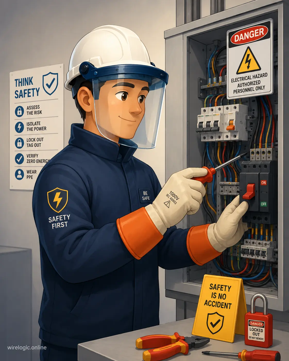
Using the wrong equipment is like bringing a raincoat into a wildfire. It may look protective, but it will not save you when conditions become extreme.
Lockout and Tagout Procedures
Before performing maintenance, lockout and tagout procedures help ensure circuits cannot accidentally become energized. Even when voltage testing must occur on live equipment, surrounding circuits should be isolated whenever possible. Proper labeling and communication between maintenance personnel can prevent fatal misunderstandings.
Tools Required for Testing 3 Phase Voltage
A successful voltage test starts with having the correct tools. The most important tool is a high-quality digital multimeter rated for the environment where it will be used. Cheap or improperly rated meters can fail catastrophically when exposed to industrial voltage spikes.
Technicians should always choose a meter with the appropriate CAT safety rating. For example, CAT III and CAT IV meters are commonly recommended for industrial and utility environments because they are designed to handle higher transient voltages safely. A meter designed only for residential work may not survive exposure to industrial switchgear.
Test leads matter just as much as the meter itself. Cracked insulation, bent probe tips, or loose connectors create unnecessary risks. Even experienced electricians sometimes overlook damaged leads because the defects appear minor. Yet one weak spot in the insulation can expose the user to lethal voltage.
Another valuable tool is a non-contact voltage tester. While it should never replace a direct measurement with a multimeter, it provides a quick way to verify whether conductors are energized before closer inspection. Many technicians use non-contact testers as an additional safety layer rather than relying on them exclusively.
Choosing the Right Multimeter
Not all multimeters are equal. Industrial environments require meters capable of withstanding voltage surges, electromagnetic interference, and harsh working conditions. Look for features such as:
- True RMS measurement capability
- High CAT safety ratings
- Fused current protection
- Durable impact-resistant construction
- Backlit display for low-light environments
Professional-grade meters may cost more upfront, but they significantly reduce safety risks and improve measurement accuracy.
Inspecting Test Leads Before Use
A quick inspection can prevent serious accidents. Check for cuts, exposed wire, melted insulation, and loose probe ends. If anything appears questionable, replace the leads immediately. Electrical testing equipment should never be used beyond its safe operating condition.
Setting the Multimeter for Accurate Voltage Readings
Setting the multimeter correctly is where many beginners make dangerous mistakes. A meter configured for current measurement instead of voltage measurement can short-circuit the system instantly when connected across phases. That mistake can destroy the meter and potentially cause severe injury.
To measure three phase voltage, the multimeter must be set to AC voltage mode. Most industrial systems use alternating current, so selecting DC voltage would provide meaningless readings. The voltage range should also match or exceed the expected system voltage. If the system normally operates at 480 volts, using a low-range setting may overload the meter.
VLL=3×VLN
This formula explains the relationship between line-to-line voltage and line-to-neutral voltage in many three phase systems. Understanding this relationship helps technicians verify whether readings are within expected operating conditions.
Before touching the probes to the system, technicians should test the meter on a known voltage source. This practice, often called “live-dead-live testing,” confirms the meter is functioning properly both before and after the measurement process.
AC Voltage Settings Explained
Modern digital multimeters usually offer multiple AC voltage ranges. Some meters auto-range automatically, while others require manual selection. Auto-ranging simplifies operation, but technicians should still understand what voltage levels to expect.
Incorrect settings can cause inaccurate readings or damage the meter. Taking a few extra seconds to confirm the configuration is far safer than rushing through the process.
Avoiding Incorrect Meter Configuration
One of the most dangerous errors involves leaving the probes connected to the current measurement ports while attempting voltage testing. This effectively creates a short circuit across the phases. Always double-check probe placement before testing energized circuits.
How to Measure Voltage Between Each Phase
Measuring voltage on a three phase system requires careful sequencing and attention to detail. Typically, technicians measure voltage between each phase conductor:
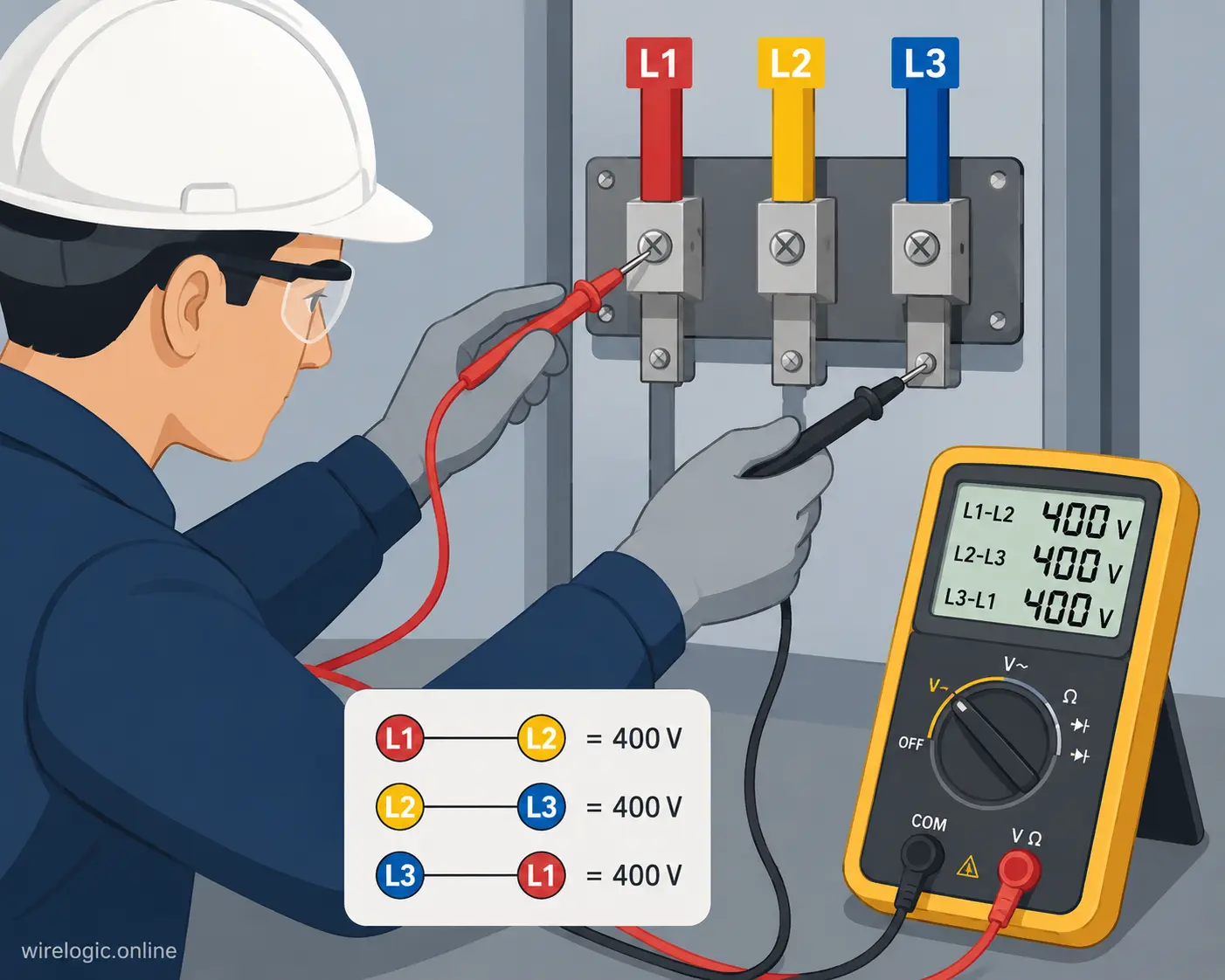
- L1 to L2
- L2 to L3
- L1 to L3
These are known as line-to-line voltage measurements. In many industrial systems, these readings should be nearly identical. Significant differences often indicate system imbalance or electrical faults.
After line-to-line measurements, technicians may also measure line-to-neutral voltage if a neutral conductor exists. These readings help identify grounding problems, transformer issues, and uneven loading conditions.
The testing process should always follow a consistent pattern. Random testing increases the chance of confusion and accidental probe contact. Experienced electricians often develop a routine similar to pilots following a preflight checklist. Consistency reduces mistakes.
Testing Line-to-Line Voltage
Line-to-line voltage measurements reveal the voltage difference between two phases. In a 480V three phase system, readings between each phase pair should typically remain close to 480 volts.
If one reading is significantly lower or higher, it may indicate:
- Loose wiring connections
- Overloaded circuits
- Damaged transformers
- Phase imbalance
- Failed breakers or contactors
Small variations are normal, but major differences require immediate investigation.
Testing Line-to-Neutral Voltage
Line-to-neutral measurements provide another layer of diagnostic information. In a 480V system configured with a neutral, line-to-neutral voltage may measure around 277 volts.
277×3≈480
These measurements help technicians determine whether the neutral conductor is functioning correctly and whether loads are balanced properly across the phases.
Step-by-Step Testing Procedure
- Wear appropriate PPE before approaching the panel.
- Verify the multimeter and leads are undamaged.
- Set the meter to AC voltage mode.
- Confirm the meter works using a known voltage source.
- Carefully place probes on the desired conductors.
- Record each voltage reading systematically.
- Compare readings for consistency.
- Remove probes safely and re-test the meter afterward.
Understanding Balanced and Unbalanced Voltage Readings
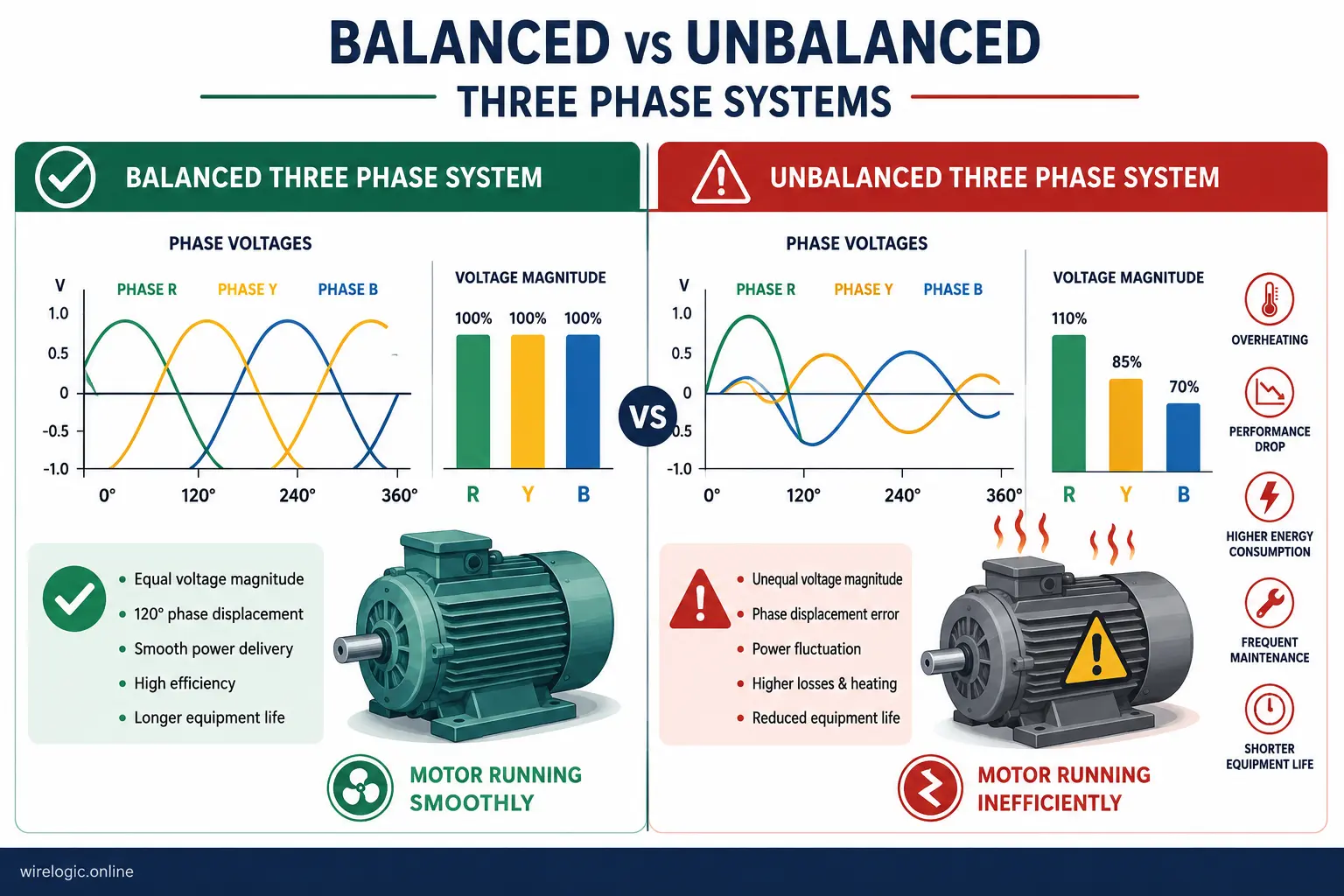
Balanced voltage is one of the clearest signs of a healthy three phase system. Ideally, all phase-to-phase measurements should remain very close in value. Minor variations are acceptable, but larger differences indicate trouble somewhere in the system.
Think of a three phase system like a three-legged stool. When all legs are equal, the stool remains stable. If one leg becomes shorter, the entire structure wobbles and strains under pressure. Electrical imbalance works the same way. Motors subjected to unbalanced voltage draw excessive current, generate extra heat, and suffer premature failure.
Voltage imbalance is especially dangerous for industrial motors. Even a small imbalance can dramatically increase motor winding temperatures. Over time, insulation deteriorates and eventually fails. Many costly motor failures begin with unnoticed voltage imbalance that slowly damages the equipment day after day.
What Balanced Readings Mean
Balanced readings usually indicate:
- Proper transformer operation
- Healthy distribution wiring
- Even electrical loading
- Stable power delivery
- Reduced stress on motors and equipment
Balanced systems operate more efficiently and experience fewer unexpected breakdowns.
Causes of Voltage Imbalance
Several issues can create imbalance in a three phase system:
| Problem | Possible Effect |
|---|---|
| Loose terminals | Voltage drop |
| Uneven loads | Phase imbalance |
| Damaged transformer windings | Irregular voltage |
| Corroded connections | Heat buildup |
| Failed contactors | Inconsistent phase delivery |
Identifying these problems early can prevent catastrophic equipment failure and expensive downtime.
Common Electrical Problems Revealed by Voltage Testing
Voltage testing is not only about confirming that power exists. It is also one of the best diagnostic tools for identifying hidden electrical issues before they escalate into dangerous failures.
Loose connections are among the most common problems uncovered during testing. A loose terminal creates resistance, and resistance creates heat. Over time, that heat can burn insulation, damage equipment, and even start electrical fires. Voltage drop measurements often reveal these weak points before visible damage appears.
Phase loss is another serious condition. When one phase disappears due to a blown fuse, failed breaker, or damaged conductor, motors may continue running temporarily on the remaining phases. This condition, often called single-phasing, can destroy motors quickly because the remaining windings become overloaded.
Electrical testing can also reveal grounding issues, overloaded circuits, transformer problems, and deteriorating components. Skilled technicians use voltage readings almost like doctors use vital signs. The numbers tell a deeper story about system health.
Loose Connections and Burned Terminals
Loose connections generate heat gradually, often without obvious warning signs at first. Thermal imaging can help locate these hotspots, but voltage testing frequently identifies abnormal drops that point technicians toward the problem area.
Ignoring loose terminals is risky because the issue rarely improves on its own. Electrical resistance typically worsens over time until catastrophic failure occurs.
Phase Loss and Motor Damage Risks
Three phase motors rely on all phases operating correctly. Losing one phase forces the remaining windings to compensate, increasing current draw and overheating the motor rapidly.
According to OSHA industry hazard guidance, electrocution and electrical equipment failures remain significant concerns in power distribution environments. Proper testing and preventive maintenance significantly reduce these risks.
Common Mistakes That Create Safety Hazards
Even experienced technicians can make mistakes during voltage testing. Unfortunately, electrical systems rarely forgive errors. One careless moment can damage expensive equipment or cause severe injury.
A common mistake involves rushing through measurements without verifying the meter configuration. Another dangerous habit is touching exposed metal probe tips during testing. Some technicians also become overly comfortable around energized systems after years of experience, leading to complacency.
Complacency is particularly dangerous in electrical work because conditions change constantly. A panel that was safe yesterday may contain hidden faults today. Damaged insulation, moisture, loose hardware, and aging equipment all increase risk levels unpredictably.
Reddit discussions among electricians and safety professionals frequently emphasize the importance of avoiding live work whenever possible and using proper arc flash precautions during necessary energized testing. Real-world incidents consistently show that small shortcuts often lead to major consequences.
Errors That Can Damage the Multimeter
Some of the most common meter-damaging mistakes include:
- Using current mode instead of voltage mode
- Exceeding the meter’s voltage rating
- Using damaged test leads
- Connecting probes incorrectly
- Attempting resistance testing on energized circuits
These errors can instantly destroy internal meter components and create dangerous arc flashes.
Unsafe Testing Habits to Avoid
Unsafe habits often develop slowly over time. Technicians may begin skipping PPE because “nothing ever happened before.” Others may test circuits one-handed while balancing awkwardly near grounded surfaces.
Safe habits should become automatic:
- Keep hands behind probe guards
- Stand on insulated surfaces
- Use one hand when possible
- Avoid unnecessary contact with grounded metal
- Follow facility safety procedures consistently
Electrical safety is built on discipline, not luck.
Conclusion
Learning how to check voltage on a three phase system is about far more than reading numbers from a multimeter screen. It requires understanding how three phase power operates, recognizing the dangers of energized systems, using the proper equipment, and interpreting readings correctly. Every voltage measurement provides valuable information about the health and stability of the electrical system.
Balanced readings usually indicate reliable operation, while unbalanced measurements can warn of loose connections, overloaded circuits, failing transformers, or dangerous phase loss conditions. Proper testing techniques help prevent costly downtime, equipment damage, and potentially life-threatening electrical accidents.
The most important lesson is that safety must always come first. Industrial electrical systems contain enough energy to cause catastrophic injuries within seconds. Careful preparation, proper PPE, accurate meter setup, and disciplined testing procedures dramatically reduce those risks. A skilled technician treats every energized conductor with respect because electricity never offers second chances.
FAQs
1. What voltage should a 3 phase system read?
The exact voltage depends on the system design. Common industrial systems measure 208V, 240V, 400V, or 480V line-to-line. The readings between phases should remain nearly equal.
2. Can I test three phase voltage with any multimeter?
No. You should use a properly rated multimeter designed for industrial electrical environments. Look for CAT III or CAT IV safety ratings.
3. What causes unbalanced voltage in a three phase system?
Voltage imbalance may result from uneven loads, loose connections, damaged transformers, corroded terminals, or failed electrical components.
4. Why is line-to-line voltage higher than line-to-neutral voltage?
In three phase systems, the relationship between these voltages is determined mathematically. Line-to-line voltage is typically the line-to-neutral voltage multiplied by the square root of three.
5. Is it safe to test live three phase circuits?
Testing energized circuits always involves risk. Only trained personnel using proper PPE, insulated tools, and approved testing procedures should perform live voltage testing.

Colt Marlowe is a 29-year-old American content writer based in Boise, Idaho. He specializes in technology, digital tools, and online business topics, combining years of research with practical experience to produce clear, trustworthy articles. As a contributor to wirelogic.online, he focuses on creating well-researched, reader-friendly content that emphasizes accuracy, transparency, and long-term value for audiences seeking reliable information.