
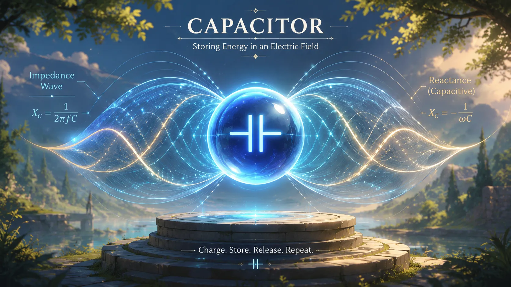
Capacitors can feel almost magical when you first encounter them in electronics. One moment they seem to block electricity completely, and the next moment they allow alternating current to pass through with surprising ease. That strange behavior is exactly why understanding capacitive impedance matters so much in electronics, electrical engineering, audio systems, communication equipment, and power circuits. If you have ever wondered why a capacitor reacts differently to AC and DC, or why frequency changes everything, you are in the right place.
The key idea behind capacitor impedance is that a capacitor does not resist current in the same way a resistor does. Instead, it creates something called capacitive reactance, which depends heavily on frequency. According to modern electronics references, the reactance of a capacitor decreases as frequency increases, meaning high-frequency signals pass through more easily while low-frequency signals are restricted.
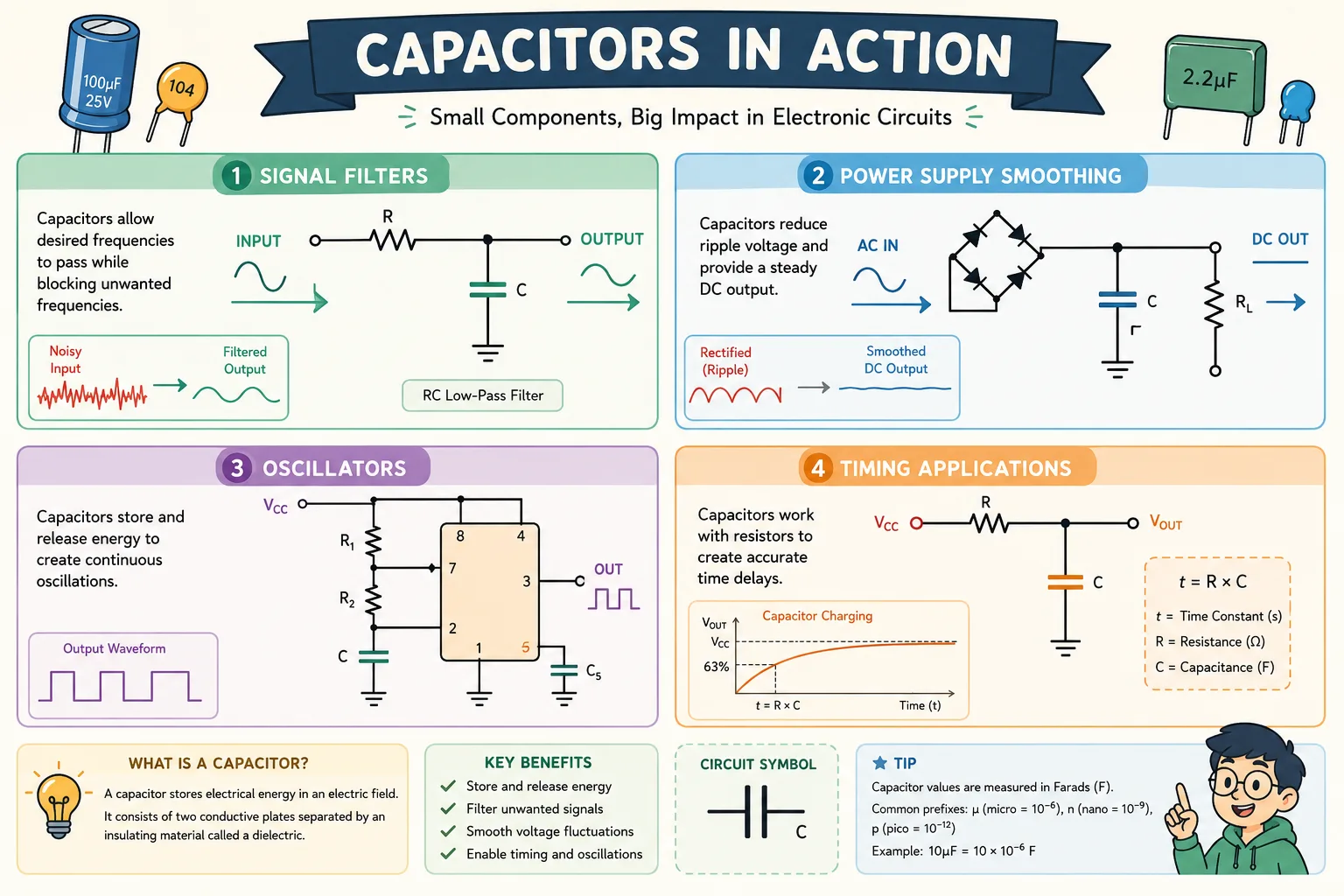
Engineers use this behavior in countless applications. Audio crossovers separate bass from treble using capacitive reactance. Power supplies smooth ripple voltages with large capacitors. Radio circuits rely on carefully chosen capacitance values to tune specific frequencies. Without understanding impedance, designing these systems would be like trying to drive through fog without headlights.
What Capacitive Impedance Really Means
Capacitive impedance describes how much a capacitor opposes alternating current. Unlike ordinary resistance, which converts electrical energy into heat, capacitive impedance temporarily stores energy in an electric field and then releases it back into the circuit. That makes capacitors dynamic components instead of passive energy burners.
The Difference Between Resistance and Reactance
Resistance stays constant regardless of frequency. A 100-ohm resistor is always 100 ohms whether the signal is DC, 60 Hz, or 1 MHz. Capacitors are completely different. Their opposition changes depending on how quickly the voltage changes over time. This frequency-dependent opposition is called reactance.
Think about a revolving door at a busy hotel. If people move slowly, the door barely rotates and movement becomes awkward. But if people move quickly and continuously, the revolving door spins smoothly. A capacitor behaves similarly. Slow-changing voltages create large opposition, while rapidly changing voltages move through much more easily.
In AC circuits, impedance combines both resistance and reactance. For a purely capacitive circuit, the impedance mainly comes from capacitive reactance. Engineers represent it using the symbol Xc and measure it in ohms.
Why Capacitors Behave Differently in AC Circuits
A capacitor consists of two conductive plates separated by an insulating material called a dielectric. When voltage is applied, electric charge builds up on the plates. In DC circuits, the capacitor eventually becomes fully charged, and current stops flowing. That is why capacitors block steady direct current.
AC behaves differently because the voltage constantly changes direction. The capacitor never fully settles. It continuously charges and discharges as the signal alternates. Because of this ongoing activity, alternating current can effectively “flow” through the capacitor even though electrons never physically cross the dielectric barrier.
This charging and discharging cycle is the heart of capacitive impedance. Faster voltage changes mean faster charge movement, which reduces opposition to current flow.
The Relationship Between Frequency and Capacitive Impedance
Frequency has an enormous effect on capacitor behavior. One small change in frequency can dramatically change the amount of current flowing through a circuit.
Why Higher Frequencies Reduce Reactance
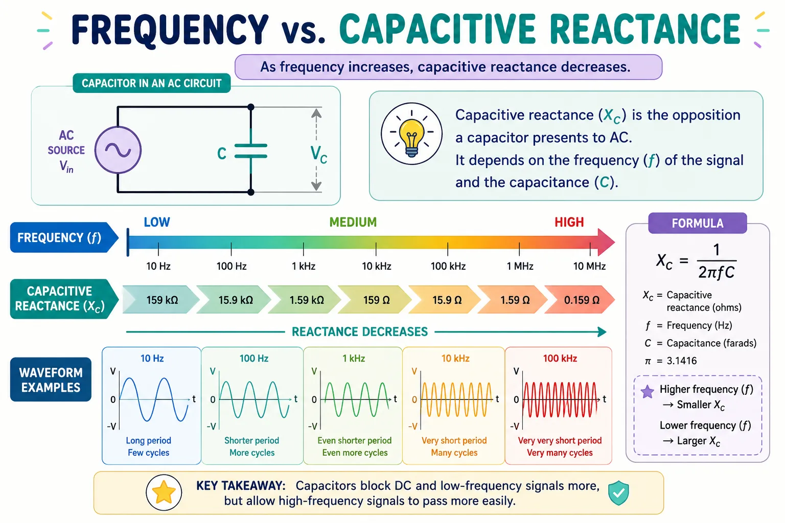
The mathematical relationship between frequency and reactance is inverse. As frequency increases, capacitive reactance decreases. This means high-frequency signals encounter less opposition.
The relationship is represented by this formula:
<math xmlns=”XC=12πfCX_C = frac{1}{2pi f C}
In this equation:
- Xc = capacitive reactance in ohms
- f = frequency in hertz
- C = capacitance in farads
Notice how frequency appears in the denominator. As frequency grows larger, the overall reactance becomes smaller. This simple relationship explains why capacitors are commonly used in filters and communication circuits.
For example, a 1 µF capacitor has a reactance of roughly 3.2 kΩ at 50 Hz, but only about 16 Ω at 10 kHz. That difference is massive. The same capacitor that strongly restricts low-frequency current barely resists higher-frequency signals.
What Happens at Zero Frequency
DC technically has a frequency of 0 Hz. When frequency approaches zero, the denominator in the reactance equation also approaches zero. That causes capacitive reactance to become extremely large; effectively infinite.
This explains why capacitors block steady DC current after charging. Once fully charged, no additional current can flow unless the voltage changes again. You can picture the capacitor as a water tank connected to a pipe. Once the tank fills completely, water stops moving unless the pressure changes.
This characteristic makes capacitors useful in coupling circuits, where engineers want AC signals to pass while blocking DC bias voltages.
Breaking Down the Capacitive Reactance Formula
At first glance, the reactance equation may seem intimidating. Once you understand each part, though, it becomes surprisingly logical.
Understanding Each Variable in the Formula
The equation contains three important elements:
<math xmlns=”XC=12πfCX_C = frac{1}{2pi f C}
- 2π comes from sinusoidal wave mathematics
- f represents signal frequency
- C represents capacitance
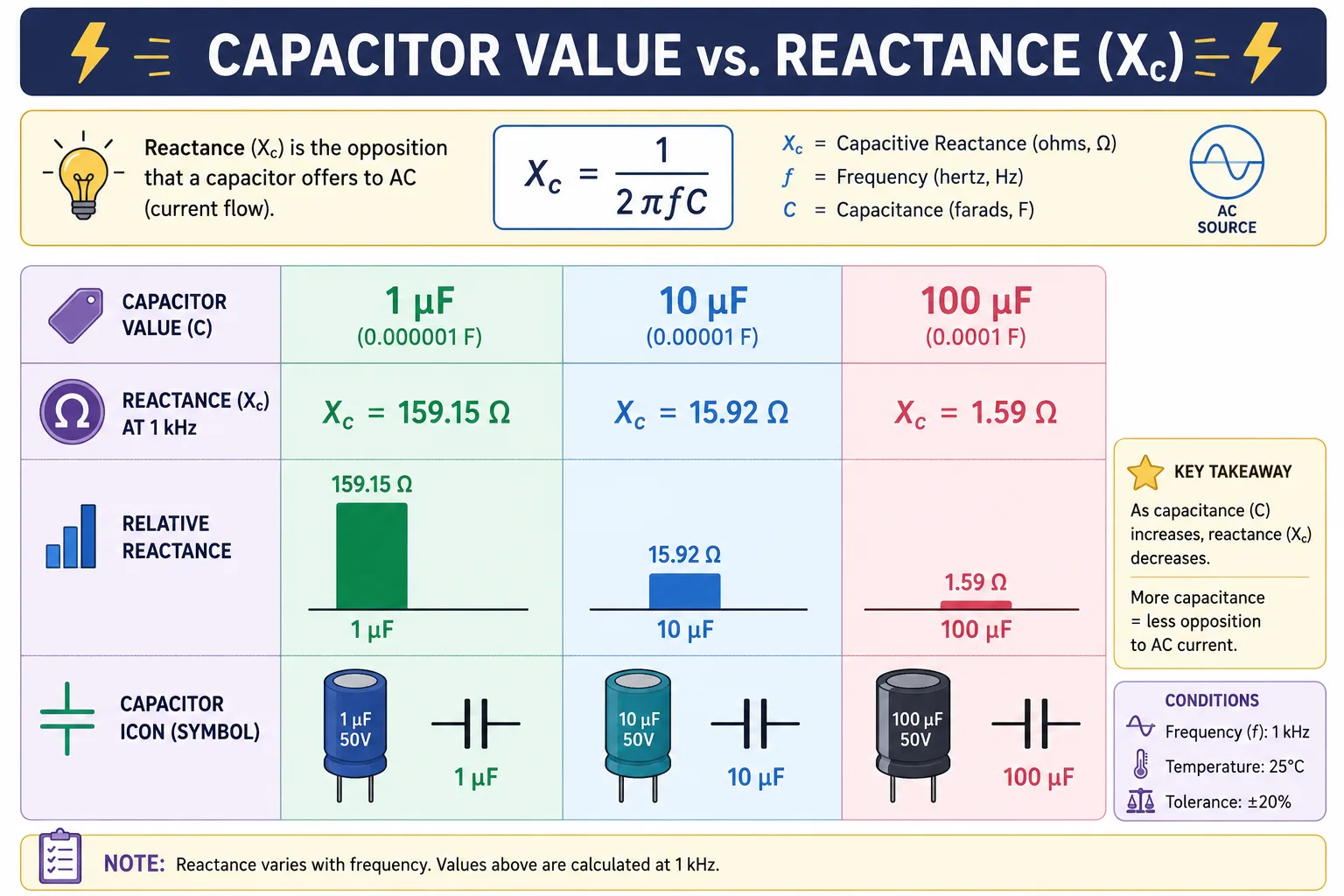
Frequency tells us how rapidly the voltage alternates. Capacitance describes how much electric charge the capacitor can store. Larger capacitors store more charge and therefore offer less reactance at the same frequency.
If you double the capacitance, reactance gets cut in half. If you double the frequency, reactance also gets cut in half.
That is why large capacitors are commonly used in low-frequency power supplies, while smaller capacitors dominate high-frequency radio circuits.
Units Used in Capacitive Reactance Calculations
One of the biggest beginner mistakes involves unit conversion. Capacitance is measured in farads, but most practical capacitors use microfarads (µF), nanofarads (nF), or picofarads (pF).
| Unit | Value in Farads |
|---|---|
| 1 µF | 0.000001 F |
| 1 nF | 0.000000001 F |
| 1 pF | 0.000000000001 F |
Failing to convert these correctly can produce wildly incorrect results. A misplaced decimal can transform a reasonable impedance value into nonsense.
How to Calculate Impedance of a Capacitor Step by Step
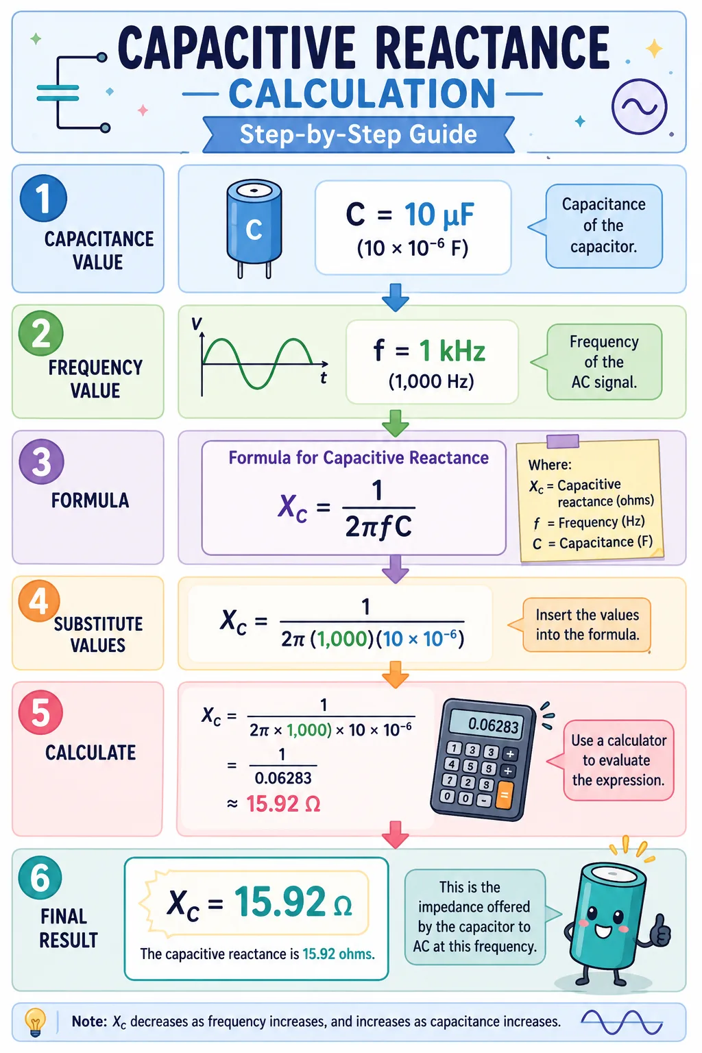
Calculating capacitive impedance becomes straightforward once you follow a consistent method.
Basic Calculation Example
Suppose you have:
- Capacitance = 10 µF
- Frequency = 60 Hz
First convert microfarads to farads:
10 µF = 10 × 10⁻⁶ F
Now apply the formula:
<math xmlns=”XC=12π(60)(10×10−6)X_C = frac{1}{2pi (60)(10 times 10^{-6})}
The result is approximately:
265 Ω
That means the capacitor opposes 60 Hz current with about 265 ohms of reactance.
Solving for Different Frequencies
Frequency dramatically changes the result even when capacitance stays constant.
Example Using 50 Hz
For a 1 µF capacitor at 50 Hz:
<math xmlns=”XC=12π(50)(1×10⁻⁶)X_C = frac{1}{2pi (50)(1 times 10^{-6})}
Result:
≈ 3183 Ω
This relatively high reactance restricts low-frequency current flow strongly.
Example Using 10 kHz
Now increase frequency to 10,000 Hz:
<math xmlns=”XC=12π(10000)(1×10⁻⁶)X_C = frac{1}{2pi (10000)(1 times 10^{-6})}
Result:
≈ 15.9 Ω
That is an enormous reduction in opposition. The same capacitor suddenly becomes highly conductive to AC signals.
Why Capacitors Resist AC Differently Than DC
The difference between AC and DC behavior confuses many beginners because it feels counterintuitive at first.
Charging and Discharging Behavior
Capacitors react to voltage changes, not steady voltage levels. In AC circuits, the voltage polarity reverses continuously. This constant change forces the capacitor into endless charging and discharging cycles.
Imagine bouncing a basketball repeatedly against the floor. The ball never stays still because energy constantly changes direction. Capacitors experience a similar rhythmic energy exchange in AC systems.
Because of this ongoing motion, current appears to flow continuously through the capacitor.
Why DC Eventually Stops Flowing
DC lacks changing polarity. Once the capacitor reaches the supply voltage, charging stops completely. At that point, the capacitor behaves like an open switch.
This characteristic is useful in timing circuits, filtering applications, and DC isolation systems. Engineers often use capacitors to separate AC signal paths from DC operating voltages.
According to electronics references, capacitors exhibit effectively infinite reactance at 0 Hz DC conditions.
How Frequency Changes Affect Current Flow
Frequency and current flow are tightly linked in capacitive circuits.
Low Frequency Effects
At low frequencies, the capacitor has plenty of time to charge fully before voltage polarity changes. Once fully charged, current temporarily slows or stops. This increases effective opposition.
This is why capacitors tend to block bass frequencies in audio systems. Low-frequency signals experience higher reactance.
In practical circuits, this behavior enables high-pass filter design. Engineers can selectively remove low-frequency noise or DC components while preserving higher-frequency signals.
High Frequency Effects
At high frequencies, voltage changes direction so quickly that the capacitor never fully charges. Current keeps moving almost continuously.
This causes reactance to fall dramatically. High-frequency signals pass through far more easily.
That is why small capacitors are commonly used for noise suppression in digital electronics. They provide low impedance paths for unwanted high-frequency interference.
Practical Examples Using Common Capacitor Values
Real-world examples make these concepts easier to visualize.
Comparing 1 µF, 10 µF, and 100 µF Capacitors
Here is a comparison at 60 Hz:
| Capacitor Value | Capacitive Reactance |
|---|---|
| 1 µF | 2652 Ω |
| 10 µF | 265 Ω |
| 100 µF | 26.5 Ω |
Larger capacitance produces lower reactance.
A 100 µF capacitor allows significantly more low-frequency current flow than a 1 µF capacitor. That is why power supply smoothing circuits use large electrolytic capacitors.
Capacitors in Audio and Power Supply Circuits
Audio systems use capacitors to separate frequency bands. Tweeters often receive signals through capacitors because high frequencies pass easily while low frequencies are attenuated.
Power supplies use capacitors differently. Large capacitors smooth pulsating DC output from rectifiers. They temporarily store energy and release it between voltage peaks.
Radio systems also rely heavily on capacitive reactance. Tuned circuits use specific capacitor and inductor combinations to select desired frequencies while rejecting others.
Mistakes That Often Lead to Wrong Calculations
Even experienced students make avoidable errors when calculating capacitive impedance.
Unit Conversion Errors
This is the most common problem by far. Many calculations fail because users forget to convert:
- µF to farads
- kHz to Hz
- mF to F
A simple conversion mistake can change results by factors of thousands or millions.
Always convert everything into base SI units before applying formulas.
Ignoring Frequency Dependence
Some beginners treat capacitive reactance like fixed resistance. That approach leads to major misunderstandings.
Capacitor impedance changes whenever frequency changes. A capacitor that behaves almost like an open circuit at low frequency may behave nearly like a short circuit at high frequency.
Ignoring this relationship causes filter calculations and timing circuits to fail.
Where Capacitive Impedance Matters in Real Circuits
Capacitive impedance appears almost everywhere in electronics.
Filters and Signal Processing
Filters rely directly on reactance behavior. High-pass filters use capacitors to block low frequencies while allowing higher frequencies to pass.
Low-pass filters often combine resistors and capacitors to remove unwanted noise.
Communication systems depend heavily on these principles. Without capacitive reactance, radios, Wi-Fi devices, and audio equipment would struggle to isolate useful signals from interference.
Power Systems and Timing Circuits
Power systems use capacitors for power factor correction and voltage stabilization. Timing circuits exploit predictable charging and discharging rates to create delays and oscillations.
Oscillators, flash circuits, switching supplies, and digital clock generators all depend on capacitor impedance behavior.
Researchers and engineers also use impedance measurements to analyze advanced systems like supercapacitors, nano-capacitors, and electrochemical devices.
Conclusion
Understanding how to calculate impedance of a capacitor opens the door to mastering AC circuit analysis. Capacitors are not mysterious once you understand their relationship with frequency. Their opposition to current, known as capacitive reactance, decreases as frequency rises and increases as frequency falls.
The formula:
<math xmlns=”XC=12πfCX_C = frac{1}{2pi f C}
explains nearly everything about capacitor behavior in AC systems. Higher frequency means lower reactance. Larger capacitance also means lower reactance. DC, which has zero frequency, results in extremely high reactance after the capacitor charges fully.
These principles power modern electronics. From audio crossovers and radio tuning circuits to power supply filters and digital communication systems, capacitive impedance shapes how signals move through real-world devices every second of the day.
FAQs
1. What is the impedance of a capacitor at DC?
At DC, frequency equals 0 Hz, so capacitive reactance becomes effectively infinite. After charging, the capacitor blocks steady current flow.
2. Why does capacitive reactance decrease with frequency?
Higher frequencies cause faster charging and discharging cycles, reducing opposition to current flow. That is why capacitors pass high-frequency signals more easily.
3. Is capacitive reactance the same as resistance?
No. Resistance dissipates energy as heat, while capacitive reactance temporarily stores and releases energy in an electric field.
4. What unit is used for capacitive reactance?
Capacitive reactance is measured in ohms (Ω), just like resistance.
5. Why are capacitors important in filters?
Capacitors allow engineers to control which frequencies pass through a circuit. This makes them essential for audio systems, radios, communication devices, and power electronics.

Colt Marlowe is a 29-year-old American content writer based in Boise, Idaho. He specializes in technology, digital tools, and online business topics, combining years of research with practical experience to produce clear, trustworthy articles. As a contributor to wirelogic.online, he focuses on creating well-researched, reader-friendly content that emphasizes accuracy, transparency, and long-term value for audiences seeking reliable information.