

Relays are one of those electrical components that look tiny and harmless but quietly do some of the heaviest lifting in electrical systems. Whether you are wiring auxiliary lights in a car, building a DIY automation setup, or troubleshooting an electrical issue, understanding relay wiring can save you from blown fuses, melted wires, and frustrating electrical failures. Many people get intimidated when they see relay terminal numbers like 85, 86, 30, and 87, but once you break them down, the whole system starts making sense like pieces of a puzzle snapping together.
Modern vehicles, industrial machines, smart home systems, and even marine electronics rely heavily on relays because they allow a low-current switch to control a high-current device safely. Industry-standard relay numbering based on the DIN 72552 standard has made troubleshooting easier across different manufacturers and systems. Recent electrical engineering references and automotive relay guides continue to emphasize that relays are essential for safely controlling high-current devices such as cooling fans, horns, lighting systems, fuel pumps, and aftermarket accessories.
Before touching wires or connecting terminals, it helps to understand why relays exist in the first place and how each terminal works together like teammates in a relay race. Once that foundation is clear, wiring one becomes much easier and safer.
Understanding What a Relay Actually Does
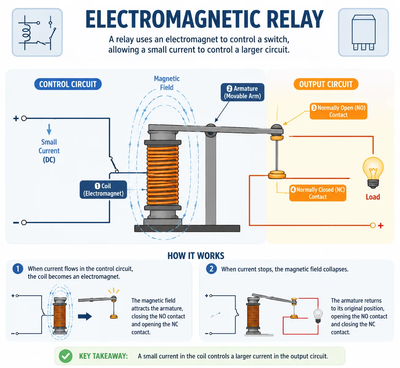
Imagine trying to use a tiny kitchen light switch to directly power a massive industrial air compressor. The switch would probably melt faster than ice cream on hot pavement. That is exactly where a relay becomes useful. A relay acts like a middleman between a low-power control circuit and a high-power electrical load. Instead of sending heavy current through a delicate switch, the relay uses a small electrical signal to activate a much larger circuit safely.
Inside the relay is an electromagnetic coil. When voltage flows through the coil, it creates a magnetic field that physically moves an internal switch. That movement either opens or closes another circuit carrying a higher current load. It sounds complicated at first, but it is really just a remote-controlled switch powered by magnetism. Automotive engineering resources continue to describe relays as electrically operated switches designed specifically for controlling high-current devices from low-current inputs.
This setup offers several major benefits. First, it keeps heavy current away from sensitive dashboard switches and control modules. Second, it reduces the need for long runs of thick wire throughout the system. Third, it improves electrical safety because the relay isolates the control side from the load side. Think of it like hiring a bodyguard for your electrical system. The small switch gives orders, but the relay handles the hard work.
Relays are used in headlights, cooling fans, fuel pumps, air horns, winches, fog lights, and countless industrial applications. In modern electronics, relays are practically everywhere because they make electrical systems more efficient, more reliable, and much easier to manage.
Why Relays Are Used in Electrical Circuits
Electrical systems can become dangerous very quickly when high current flows through undersized wires or switches. One of the main reasons relays exist is to prevent those problems before they happen. A relay allows a low-current trigger circuit to safely control a much larger electrical load without placing stress on the control switch itself.
For example, a typical automotive relay coil may only require around 150 to 200 milliamps to activate, yet the contacts can switch loads rated at 20, 30, or even 80 amps depending on the relay design. That difference is huge. Without a relay, you would need bulky switches, thick dashboard wiring, and far more complex electrical routing.
Another major advantage is heat management. High-current wiring generates heat, especially under load. Engineers prefer keeping that heat away from sensitive control systems like ECUs, switches, or control panels. Relays allow the heavy current path to stay short and direct while the control wire remains thin and lightweight. It is similar to using a small remote control to operate a giant machine from a safe distance.
Community discussions among automotive electricians also consistently point out that relays help reduce voltage drop and improve overall reliability in accessory installations like light bars, fog lamps, and aftermarket fans. When properly installed with the correct fuse and wire gauge, relays make electrical systems cleaner, safer, and more professional.
A Closer Look At Relay Terminal Numbers
One of the most confusing parts for beginners is understanding the terminal numbers printed on the relay housing. At first glance, numbers like 85, 86, 30, and 87 seem random, but they actually follow a standardized system used worldwide. This numbering convention comes from the DIN 72552 standard used in automotive and industrial electrical systems.
The two most important control-side terminals are 85 and 86.
| Terminal | Function |
|---|---|
| 85 | Coil ground or negative |
| 86 | Coil positive trigger |
| 30 | Main power input |
| 87 | Normally open output |
| 87a | Normally closed output |
Terminal 85 is usually connected to ground, while terminal 86 receives the trigger voltage. When voltage is applied across these terminals, the electromagnetic coil activates and pulls the internal switch closed.
<math xmlns=”V=IRV = IR
<math xmlns=”VsV_s
V<math xmlns=”RR
<math xmlns=”ΩOmega
<math xmlns=”I=VsR=12.0 V6.0 Ω=2.00 AI = frac{V_s}{R} = frac{12.0,mathrm{V}}{6.0,Omega} = 2.00,mathrm{A}
Source voltage in volts drives the same loop current through the whole one-resistor circuit, and resistance in ohms limits that current, using Ohm’s law. Resistance is constrained from 0.5 to 20 ohms. The resistor’s inner pipe narrows as a visual cue for higher resistance, not as a literal mechanical clamp. The blue arrow and resistor markers are qualitative conventional current cues, not microscopic charge-speed measurements. In this one-resistor model, the source voltage equals the resistor voltage drop; heating, power limits, and non-ohmic behavior are not shown.Vs = 12.0 V+-R = 6.0 ΩI = 2.00 A
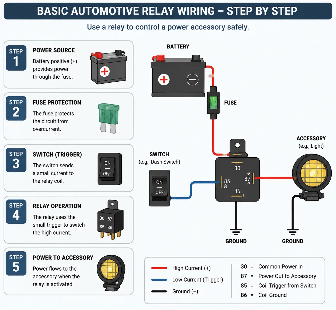
Terminal 30 is the common power input. This terminal usually receives fused battery power. Terminal 87 becomes connected to terminal 30 when the relay energizes. In a 5-pin relay, terminal 87a represents the normally closed path, meaning it remains connected to terminal 30 until the relay activates.
Think of the relay like a railroad switchyard. The control side tells the track where to go, while the load side handles the heavy traffic. Once you understand which terminals belong to the coil and which belong to the load circuit, reading wiring diagrams becomes much easier.
How the Control Side and Load Side Work Together
Every relay contains two separate circuits working together simultaneously. The first is the control side, also called the coil side. The second is the load side, which handles the larger electrical current. Understanding this separation is the secret to mastering relay wiring.
The control side usually consists of terminals 85 and 86. When a switch sends voltage to the coil, the magnetic field activates. This side consumes very little current compared to the load side. That is why small switches and lightweight wiring can safely operate large devices through relays.
The load side typically uses terminals 30 and 87. Terminal 30 receives power directly from the battery or power distribution source through a fuse. Once the relay coil energizes, the internal switch closes and allows current to flow from terminal 30 to terminal 87, powering the connected device.
Many troubleshooting experts explain relay operation using the concept of two entirely separate loops. One loop triggers the relay, while the other carries the actual working current. That distinction matters because beginners sometimes accidentally wire the high-current device through the switch instead of the relay contacts, defeating the entire purpose of the relay.
Picture it like a drawbridge. The control side presses the button to raise the bridge, while the load side carries the heavy traffic. They cooperate, but each has a completely different job. Once you visualize relay circuits this way, diagnosing problems becomes far easier.
Choosing the Right Power Source and Fuse
A relay is only as safe as the power source and fuse protecting it. One of the most dangerous mistakes people make is connecting a relay directly to battery power without proper fuse protection. That can lead to melted wires, burned components, or even electrical fires.
The fuse should always be installed as close to the battery or power source as possible. Electrical professionals and experienced automotive installers consistently recommend keeping the fuse within about six inches of the power source. The purpose of the fuse is not mainly to protect the relay itself. It protects the wiring from excessive current during a short circuit or overload condition.
Choosing the correct fuse size depends on wire gauge and current demand. A common mistake is selecting a fuse based only on the accessory rather than the wire capacity. Online discussions among experienced installers frequently emphasize that the fuse must match the wire’s safe current rating.
Here is a simplified comparison:
| Wire Gauge | Typical Safe Current |
|---|---|
| 18 AWG | 10 amps |
| 16 AWG | 13 amps |
| 14 AWG | 15 amps |
| 12 AWG | 20–25 amps |
| 10 AWG | 30–40 amps |
Using undersized wire creates resistance and heat buildup. Using an oversized fuse removes protection entirely. That combination is like locking the fire extinguisher away during a kitchen grease fire. Proper fuse selection and wire sizing are critical for both performance and safety.
Step-by-Step Relay Wiring for a Basic Setup
Wiring a relay becomes much easier when broken into clear, manageable steps. A standard 4-pin relay is usually the simplest place to begin. Most automotive relay wiring diagrams follow the same general structure regardless of application.
Tools and Materials Needed
Before starting, gather the following:
- 4-pin or 5-pin relay
- Inline fuse holder
- Correct fuse size
- Wire cutters and crimpers
- Ring terminals
- Electrical tape or heat shrink
- Multimeter
- Relay socket if available
Basic 4-Pin Relay Wiring Process
- Connect terminal 30 to fused battery power.
- Connect terminal 87 to the accessory or device.
- Connect terminal 85 to ground.
- Connect terminal 86 to the trigger switch or control signal.
When the switch activates terminal 86, the relay coil energizes and connects terminal 30 to terminal 87 internally. That sends battery power directly to the load.
<math xmlns=”P=VIP = VI
For a 5-pin relay, terminal 87a adds a normally closed path. That means terminal 30 connects to 87a until the relay activates, after which the connection switches to terminal 87 instead. This design is useful for changeover circuits or reversing polarity systems.
The key to clean relay wiring is organization. Route wires carefully, secure them away from heat sources, and use quality crimps instead of twisted wire connections. A neat relay installation is usually a reliable relay installation.

Common Mistakes That Cause Relay Failure
Relay failures are often blamed on defective parts when the real problem is poor wiring practice. One of the most common mistakes is reversing the terminals. Beginners sometimes connect the load directly to the wrong pin or forget that terminal 85 and 86 belong to the coil circuit rather than the power circuit.
Another common issue is using an incorrect fuse rating. Oversized fuses may not blow during overload conditions, allowing wires to overheat dangerously. Undersized fuses blow constantly and create unnecessary troubleshooting headaches. Electrical communities frequently warn that incorrect fuse selection is among the top causes of relay-related electrical problems.
Poor grounding is another silent killer. A weak ground connection can cause erratic relay clicking, intermittent operation, voltage drops, and overheating. Many installers focus heavily on the positive wire while neglecting the ground path entirely. That is like building a highway with no exit ramp.
Moisture and vibration also damage relays over time. Automotive relays installed near engines, wheel wells, or exposed areas should be weatherproofed properly. Corrosion inside terminals increases resistance and eventually leads to failure.
One especially dangerous mistake is bypassing the relay entirely by routing heavy current through the dashboard switch. This defeats the purpose of the relay and may overheat the switch wiring. Experts consistently explain that the switch should only control the coil side, not the main load circuit.
Testing the Relay Connection Safely
Testing a relay properly requires patience and a few basic tools. A multimeter is the most valuable tool during relay troubleshooting because it allows you to verify voltage, continuity, and ground integrity.
Start by listening carefully when activating the relay. A healthy relay usually produces a distinct clicking sound when the coil energizes. No click often means the coil is not receiving voltage or ground. Continuous clicking may indicate low voltage or unstable power.
Use the multimeter to check for voltage at terminal 30. This terminal should have constant fused battery power. Next, verify that terminal 86 receives trigger voltage when the switch activates. Terminal 85 should show a clean ground connection.
When the relay activates, continuity should appear between terminal 30 and terminal 87.
<math xmlns=”I=VRI = frac{V}{R}
<math xmlns=”VsV_s
V<math xmlns=”RR
<math xmlns=”ΩOmega
<math xmlns=”I=VsR=12.0 V6.0 Ω=2.00 AI = frac{V_s}{R} = frac{12.0,mathrm{V}}{6.0,Omega} = 2.00,mathrm{A}
Source voltage in volts drives the same loop current through the whole one-resistor circuit, and resistance in ohms limits that current, using Ohm’s law. Resistance is constrained from 0.5 to 20 ohms. The resistor’s inner pipe narrows as a visual cue for higher resistance, not as a literal mechanical clamp. The blue arrow and resistor markers are qualitative conventional current cues, not microscopic charge-speed measurements. In this one-resistor model, the source voltage equals the resistor voltage drop; heating, power limits, and non-ohmic behavior are not shown.Vs = 12.0 V+-R = 6.0 ΩI = 2.00 A
If voltage reaches the relay but the device still does not operate, inspect the output wire and load itself. Troubleshooting professionals often emphasize dividing the circuit into sections and testing each section individually. That method prevents random guessing and makes diagnosis much faster.
Safety matters during testing. Always disconnect battery power before modifying wiring. Avoid touching exposed terminals while circuits are energized, especially in higher-voltage industrial systems. Electricity does not give second chances very often.
Signs the Wiring Is Not Working Correctly
Bad relay wiring usually leaves clues long before total failure occurs. The most obvious symptom is a device that simply refuses to turn on. However, many electrical problems appear more subtly.
Intermittent operation is one common warning sign. Lights may flicker, fans may start slowly, or accessories may work only occasionally. That usually points toward loose terminals, poor grounds, or voltage drops.
Another symptom is excessive heat around the relay or wiring. Warm components are normal under heavy load, but hot wires, melted insulation, or burnt plastic smells indicate serious trouble. Excessive resistance caused by undersized wire or corroded connections creates dangerous heat buildup.
Rapid clicking is another major indicator. A relay that chatters repeatedly often suffers from unstable voltage supply or insufficient grounding. This problem can damage the relay contacts over time because the contacts repeatedly open and close under load.
Blown fuses also tell an important story. A single blown fuse may result from temporary overload, but repeated fuse failures usually signal short circuits, incorrect wiring, or overloaded accessories.
In some cases, replacing the relay is the correct solution. Relay contacts wear out mechanically after thousands of cycles, especially in high-current applications. If the wiring tests correctly but the relay fails to switch reliably, installing a new relay may solve the issue immediately.
Conclusion
Learning how to wire up a relay transforms electrical systems from confusing tangles of wires into organized, logical circuits. Once you understand the difference between the control side and the load side, relay diagrams become far less intimidating. The standardized terminal numbering system makes troubleshooting easier across vehicles, industrial systems, and DIY projects.
Relays are used because they improve safety, reduce heat, protect switches, and allow low-current circuits to control powerful devices efficiently. Proper fuse selection, correct wire sizing, and clean grounding practices are just as important as the relay itself. Even the best relay cannot compensate for poor wiring habits.
The good news is that relay wiring follows predictable rules. Terminal 85 and 86 control the coil. Terminal 30 supplies power. Terminal 87 delivers switched output. Once those concepts click into place, wiring relays becomes more like assembling building blocks than solving a mystery.
Whether you are installing aftermarket lights, designing automation systems, or troubleshooting electrical faults, mastering relay wiring is one of the most valuable electrical skills you can develop.
FAQs
1. What happens if I wire a relay backwards?
Most standard relays will simply fail to operate correctly if wired improperly. Reversed terminals may prevent the coil from energizing or may send power to the wrong circuit. In some cases, incorrect wiring can blow fuses or damage components.
2. Can a relay work without a fuse?
Technically yes, but it is extremely unsafe. The fuse protects the wiring and connected devices from overloads or short circuits. Running relay circuits without proper fuse protection can create fire hazards.
3. Why does my relay click but not power the device?
This usually means the control side is functioning but the load side has a problem. Possible causes include damaged contacts, no power at terminal 30, broken output wiring, or a failed accessory.
4. What is the difference between a 4-pin and 5-pin relay?
A 4-pin relay has one switched output path. A 5-pin relay adds terminal 87a, which provides a normally closed connection when the relay is inactive.
5. How do I know what fuse size to use with a relay?
The fuse should match the safe current capacity of the wire and the expected load current. Always size the fuse according to wire gauge and accessory demand to avoid overheating or nuisance fuse failures.

Colt Marlowe is a 29-year-old American content writer based in Boise, Idaho. He specializes in technology, digital tools, and online business topics, combining years of research with practical experience to produce clear, trustworthy articles. As a contributor to wirelogic.online, he focuses on creating well-researched, reader-friendly content that emphasizes accuracy, transparency, and long-term value for audiences seeking reliable information.