

Air compressors look simple from the outside. Flip a switch, hear the motor roar to life, and compressed air starts filling the tank. But behind that familiar hum sits one of the most important components in the entire system: the pressure switch. This small electrical device acts like the brain of the compressor, telling the motor exactly when to start and when to stop. Wire it incorrectly, and the compressor may refuse to start, trip breakers, overheat, or worse, create a serious electrical hazard.
A lot of DIY users assume wiring a pressure switch is just about connecting a few random wires. It is not. Proper wiring requires understanding voltage, terminal identification, safe isolation procedures, and pressure calibration. Even experienced workshop owners occasionally make mistakes that prevent startup or damage the switch itself.
Safety matters here more than most people realize. OSHA and industrial safety organizations continue reporting thousands of lockout/tagout violations every year related to hazardous energy control. Recent safety data shows proper energy isolation procedures can prevent roughly 120 fatalities and nearly 50,000 injuries annually in the United States.
This guide walks through everything step by step in plain English. Whether you are replacing an old switch, upgrading a compressor, or troubleshooting startup issues, you will learn exactly how to wire a pressure switch safely and correctly.
Understanding the Role of the Pressure Switch
What the Pressure Switch Controls in an Air Compressor
The pressure switch is the automatic traffic controller of an air compressor system. Think of it like the thermostat in your home. A thermostat tells the furnace when to start heating and when to stop. In the same way, the pressure switch monitors tank pressure and controls the compressor motor based on preset pressure limits.
When the tank pressure drops below the cut-in pressure, the switch closes the electrical circuit and powers the motor. Once the tank reaches the cut-out pressure, the switch opens the circuit and shuts the motor off. Without this automatic cycle, the compressor would either run continuously or never start at all.
Most residential air compressors operate within a range such as 90 PSI cut-in and 120 PSI cut-out. Industrial systems may operate at much higher pressures depending on the application. The switch also works alongside the unloader valve, which releases trapped air from the pump head after shutdown. That little hiss you hear after the compressor stops? That is the unloader valve doing its job.
People often underestimate how much stress this tiny switch handles. Every startup cycle sends electrical current through the contacts, and every shutdown interrupts that current. Over time, contacts wear down, springs weaken, and terminals loosen. That is why proper installation and wiring matter so much. A poorly wired pressure switch is like putting cheap tires on a race car. The whole system becomes unreliable.
Why Correct Wiring Matters for Compressor Performance
Incorrect wiring does not just stop the compressor from working. It can shorten motor life, damage the pressure switch, overheat wires, and create fire hazards. One loose terminal screw can create resistance and heat buildup that eventually melts the switch housing.
Voltage mismatches are another common problem. Many air compressors operate on either 120V or 240V systems, and wiring the switch for the wrong voltage can instantly destroy electrical components. Imagine plugging a tiny phone charger into industrial power equipment. That mismatch creates chaos fast.
Correct wiring also affects motor startup torque. Compressors require significant electrical current when starting. If the wiring is undersized or improperly connected, the motor may hum without starting, trip the breaker repeatedly, or overheat during operation. That is why manufacturers specify exact wiring diagrams and amperage ratings.
Industrial safety experts consistently emphasize proper hazardous energy control because electrical mistakes remain one of the leading causes of maintenance injuries. OSHA data continues showing thousands of annual lockout/tagout citations tied to unsafe maintenance practices.
A correctly wired pressure switch creates reliability, efficiency, and safety. A poorly wired one becomes a ticking time bomb hiding under a plastic cover.
Tools and Safety Preparation Before Wiring
Essential Tools You Need Before Starting
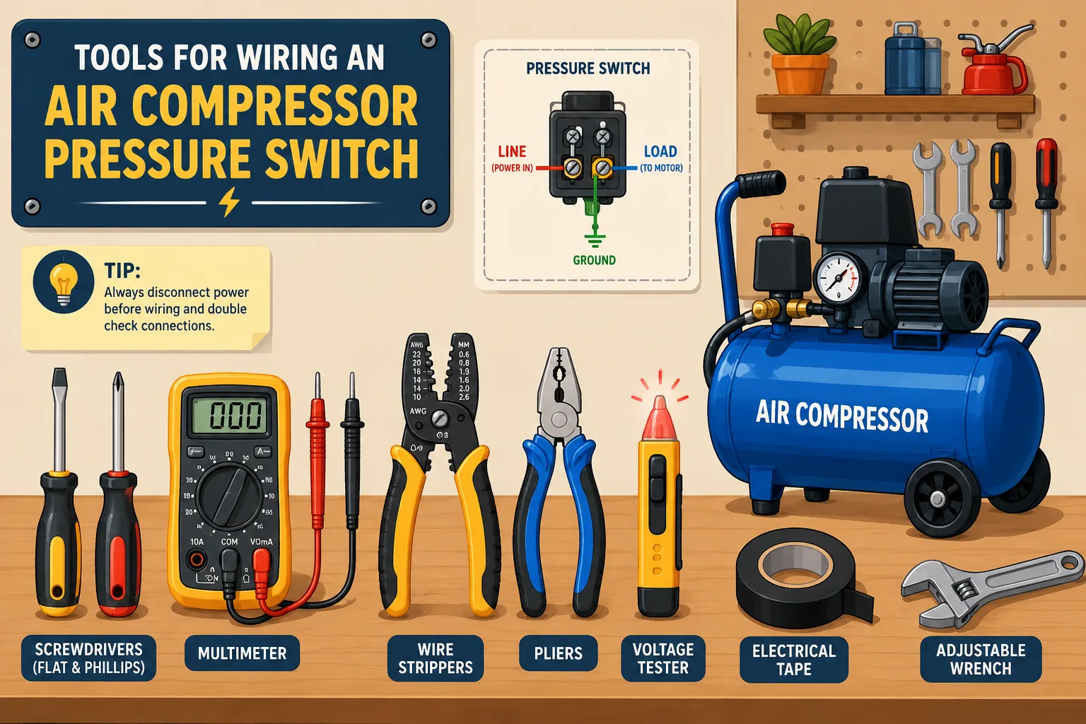
Before touching any wiring, gather the right tools. Trying to improvise electrical work with random household tools is like performing surgery with kitchen utensils. You may get through it, but the risks rise dramatically.
You will typically need:
| Tool | Purpose |
|---|---|
| Screwdrivers | Removing switch cover and terminals |
| Wire strippers | Preparing clean wire ends |
| Multimeter | Checking voltage and continuity |
| Needle nose pliers | Handling wire connections |
| Electrical tape | Insulating connections |
| Adjustable wrench | Removing fittings |
| Voltage tester | Confirming power isolation |
A multimeter is especially important. Never assume wires are dead just because the switch is off. Electrical systems sometimes contain residual voltage, shared circuits, or incorrect breaker labeling. A quick voltage test could literally save your life.
You should also inspect the new pressure switch carefully before installation. Confirm voltage ratings, amperage capacity, and PSI range match the compressor requirements. Many switches look identical externally but have different internal configurations.
Safe Power Isolation Before Starting the Work
This step is non-negotiable. Disconnecting electrical power is the foundation of safe compressor wiring. Before removing a single wire, shut off the breaker supplying power to the compressor and verify zero voltage using a tester or multimeter.
Industrial electricians follow a process called lockout/tagout, often shortened to LOTO. This procedure prevents accidental energizing of equipment during maintenance. OSHA estimates proper lockout/tagout procedures prevent approximately 120 deaths and tens of thousands of injuries every year.
Even home workshop users should adopt the same mindset. Put tape over the breaker, leave a warning note, or physically disconnect the plug if possible. You do not want someone restoring power while your hands are inside the switch housing.
Compressed air itself is also hazardous. Drain tank pressure completely before beginning work. Residual air pressure can unexpectedly move components or release stored energy during disassembly.
Explore Further: How Long Should a Car Battery Last Without Driving in Daily Use
Why Lockout and Tagout Procedures Matter
A lot of injuries happen because people think, “I’ll only be working on this for a minute.” That mindset causes accidents. Electricity does not care whether the repair takes ten seconds or ten hours.
Recent discussions among industrial maintenance workers repeatedly emphasize how dangerous bypassing lockout procedures can be. Workers describe situations where improperly energized equipment nearly caused fatal electrocution incidents.
The principle is simple: zero energy state before work begins.
That means:
- Electrical power disconnected
- Air pressure released
- Moving parts stopped
- Verification completed
Treat the compressor like a sleeping bear. Even when quiet, it can still become dangerous instantly if disturbed carelessly.
Understanding Pressure Switch Terminals
Identifying Line and Motor Terminals Correctly
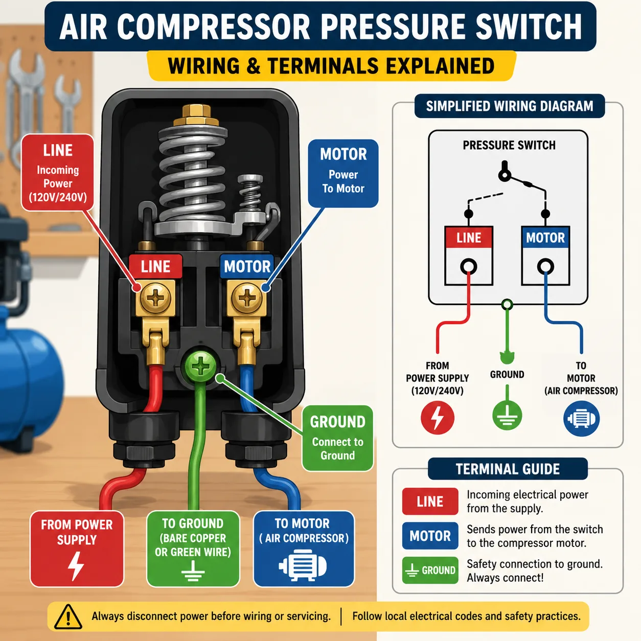
Inside the pressure switch, you will usually see two sets of terminals labeled LINE and MOTOR. These labels matter enormously.
The LINE terminals receive incoming electrical power from the breaker panel. The MOTOR terminals send power onward to the compressor motor. Mixing them up can prevent operation or damage components.
Most single-phase pressure switches use four terminals:
| Terminal Type | Function |
|---|---|
| Line 1 (L1) | Incoming power |
| Line 2 (L2) | Incoming power |
| Motor 1 (T1) | Outgoing motor wire |
| Motor 2 (T2) | Outgoing motor wire |
Some switches also include grounding screws or additional auxiliary terminals.
One easy trick is to follow the wires physically. Incoming supply wires generally enter from the electrical panel side, while motor wires run directly toward the compressor motor housing.
Always reference the manufacturer’s wiring diagram. Never rely solely on wire colors because older installations may not follow modern color standards.
Matching Voltage and Wiring Requirements
Voltage matching is absolutely critical. Most small compressors use either:
- 120V single phase
- 240V single phase
- 208V or 480V three phase for industrial systems
Using the wrong voltage configuration is like forcing diesel into a gasoline engine. Something will fail quickly.
Check the compressor motor nameplate carefully. It will specify:
- Voltage rating
- Full load amperage
- Wiring configuration
- Phase type
Then compare those numbers with the pressure switch rating.
For example:
| Compressor Voltage | Recommended Switch Rating |
|---|---|
| 120V | 120V rated switch |
| 240V | 240V rated switch |
| 3-phase industrial | Matching industrial pressure switch |
Undersized switches overheat under load. Oversized switches may fail to trip properly or operate inconsistently.
Single Phase vs Three Phase Wiring Differences
Single-phase compressors dominate residential garages and small workshops. Wiring them is relatively straightforward because only two hot wires and a ground are involved.
Three-phase systems are more complex. These are common in factories, automotive shops, and industrial facilities. Three-phase compressors may use magnetic starters alongside the pressure switch because the switch itself cannot safely handle high current loads directly.
Think of a magnetic starter as a relay assistant. The pressure switch sends a small control signal while the starter handles heavy motor current safely.
If you are working on a three-phase compressor and feel uncertain, consulting a licensed electrician is the safest path. Industrial voltage mistakes can become catastrophic very quickly.
Step-by-Step Air Compressor Pressure Switch Wiring
Removing the Old Pressure Switch Safely
Start by confirming power isolation again. Then remove the switch cover carefully using the correct screwdriver.
Before disconnecting anything, take clear photos of the existing wiring. This simple step saves enormous frustration later. Your smartphone becomes a backup wiring diagram instantly.
Label wires using masking tape if necessary. Disconnect wires one at a time rather than pulling everything loose simultaneously.
Once wires are disconnected:
- Release remaining tank pressure
- Remove mounting screws
- Unscrew the pressure switch from the manifold
- Inspect fittings for damage or corrosion
Sometimes old thread sealant hardens and makes removal difficult. Use controlled pressure with a wrench instead of excessive force that could crack fittings.
Connecting the Incoming Power Wires
Route incoming power wires neatly into the switch housing using strain relief connectors if required. Loose or unsupported wires can vibrate over time and damage terminals.
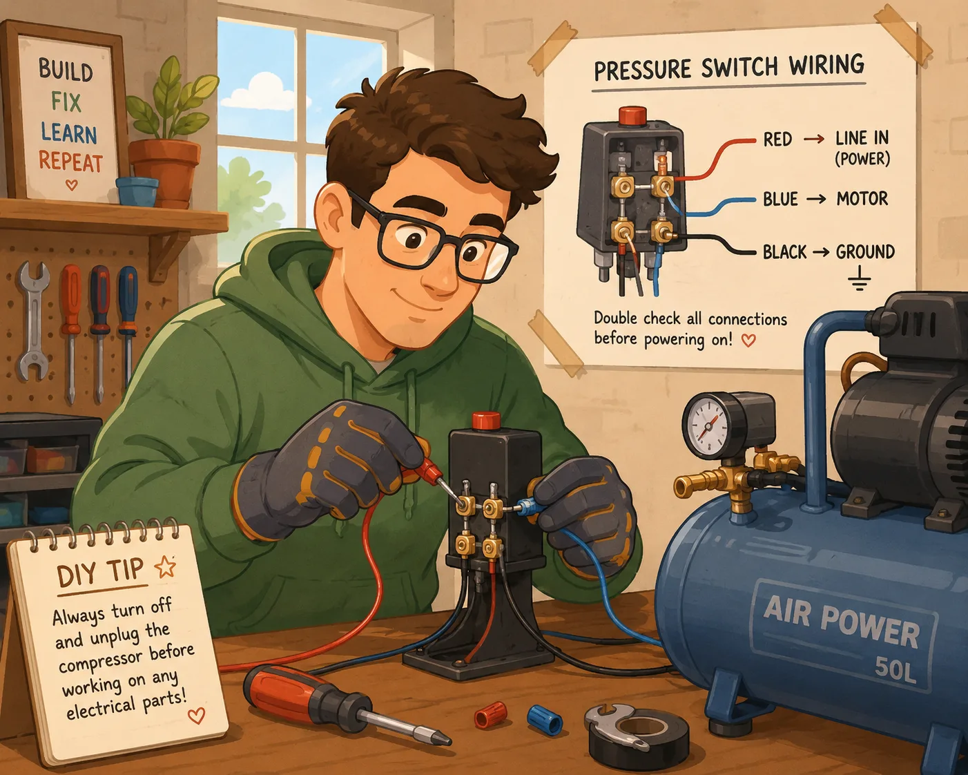
Connect the power wires to the LINE terminals exactly as indicated on the switch diagram. Tighten screws firmly but avoid overtightening. Crushing terminals can damage internal contacts or strip threads.
A clean connection matters more than brute force. Wire strands should sit fully inside the terminal clamp without fraying outward.
Loose connections are one of the most common causes of compressor startup failures. They also generate heat, which gradually destroys switch contacts.
Must Explore: What Is the White Wire on a Thermostat and Its Function
Connecting the Motor Wires Properly
Next, connect motor leads to the MOTOR terminals.
Match each conductor carefully. If the compressor includes a capacitor-start motor or magnetic starter system, follow the manufacturer’s diagram exactly. Some motors require specific jumper arrangements for voltage selection.
This is where many DIY users make mistakes. They assume any wire can go anywhere as long as electricity flows. Electric motors are far less forgiving than household lamps.
After connecting wires:
- Tug gently to confirm secure attachment
- Keep wires organized
- Avoid sharp bends
- Ensure insulation remains intact
Ground Wire Placement and Electrical Safety
The ground wire is your emergency escape path for fault current. Never ignore or bypass grounding.
Attach the ground wire securely to the green grounding screw or designated ground terminal inside the switch housing. Metal compressor frames must remain properly grounded at all times.
Without grounding, a short circuit could energize the compressor tank itself. Touching the tank could then expose someone to dangerous electric shock.
Electrical safety experts often compare grounding to a lightning rod. It safely redirects dangerous energy away from people and equipment.
Connecting the Wires Without Damaging the Switch
Pressure switches are durable but not indestructible. Excessive force during wiring can crack plastic housings, bend terminals, or weaken internal mechanisms.
Use the correct screwdriver size to avoid stripping screws. Do not yank wires sideways while tightening. Keep conductors straight and aligned.
One of the biggest hidden mistakes is leaving copper strands exposed outside the terminal. Those stray strands can contact adjacent terminals and create short circuits.
A good wiring job looks clean, organized, and intentional. Professional electricians often say neat wiring is safer wiring because problems become easier to identify later.
Adjusting and Testing the Pressure Switch
Adjusting Cut In and Cut Out Pressure Settings
Most pressure switches include adjustment screws beneath the cover. These control the compressor’s operating pressure range.
The two main settings are:
- Cut-in pressure: pressure where compressor starts
- Cut-out pressure: pressure where compressor stops
For example:
| Setting | Typical PSI |
|---|---|
| Cut-in | 90 PSI |
| Cut-out | 120 PSI |
Many switches use one large spring and one smaller spring. The large spring changes overall pressure range, while the smaller spring adjusts differential pressure between cut-in and cut-out points.
Adjust slowly and test frequently. Over-adjusting can overstress the compressor motor or exceed tank pressure ratings.
Never exceed manufacturer pressure limits. Compressor tanks are pressure vessels, not indestructible steel drums.
Common Wiring Errors That Prevent Startup
A compressor that refuses to start usually points toward a few common mistakes.
Typical issues include:
| Problem | Result |
|---|---|
| Reversed line and motor wires | Compressor will not operate correctly |
| Loose terminals | Intermittent startup |
| Incorrect voltage | Motor overheating or failure |
| Missing ground | Shock hazard |
| Incorrect pressure settings | Compressor cycles improperly |
Sometimes the issue is mechanical rather than electrical. A faulty unloader valve can trap pressure against the pump head, making startup difficult.
Another common mistake is failing to tighten wire clamps properly. Vibration gradually loosens weak connections over time.
Reddit discussions among maintenance professionals frequently highlight how seemingly minor electrical shortcuts become serious safety risks later.
Testing the Compressor After Installation
Once wiring is complete:
- Reinstall the switch cover
- Restore power
- Observe startup carefully
- Listen for unusual sounds
- Monitor pressure rise
- Verify automatic shutoff
The compressor should start smoothly when tank pressure drops below cut-in level. It should stop automatically at cut-out pressure without excessive sparking or buzzing from the switch.
Watch for warning signs like:
- Burning smell
- Arcing sounds
- Excessive heat
- Repeated breaker trips
- Slow startup
If anything seems abnormal, disconnect power immediately and recheck wiring.
Testing is not just about seeing whether the compressor runs. It is about confirming safe, stable, reliable operation under real conditions.
Troubleshooting and Maintenance Tips
Signs Your Pressure Switch Is Failing
Pressure switches wear out eventually. Even perfectly wired systems experience component fatigue over time.
Common symptoms include:
- Compressor will not start
- Compressor never shuts off
- Rapid cycling
- Visible contact burning
- Clicking without motor engagement
- Air leaks from switch area
Burned contacts are especially common in older compressors. Every startup cycle creates a tiny electrical arc that slowly erodes metal surfaces.
Environmental conditions also matter. Dust, vibration, humidity, and oil contamination shorten switch lifespan dramatically.
If the switch housing feels unusually hot or smells burnt, replacement is usually safer than repair.
Maintenance Practices That Extend Switch Life
Pressure switch maintenance is surprisingly simple.
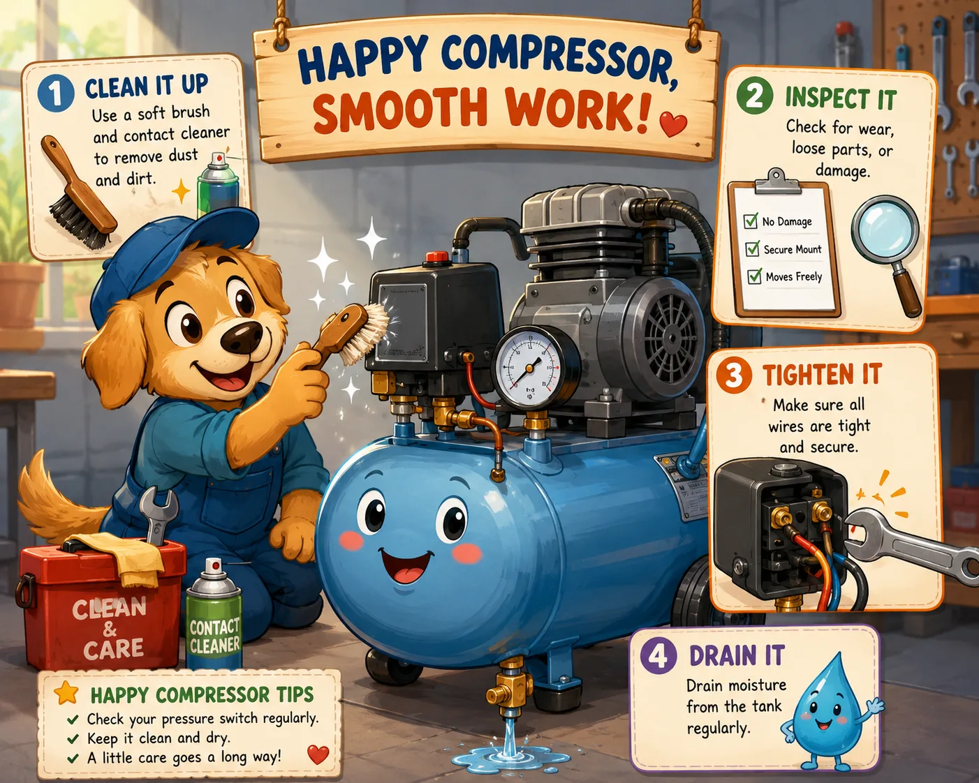
A few habits make a huge difference:
- Keep the compressor clean
- Drain tank moisture regularly
- Inspect terminals annually
- Tighten loose connections
- Replace damaged insulation
- Avoid overloading the compressor
Moisture is a hidden enemy because it promotes corrosion inside electrical contacts. Regular tank draining reduces humidity throughout the system.
Also pay attention to compressor cycling frequency. Excessive short cycling increases electrical wear dramatically. If the compressor turns on and off constantly, tank leaks or pressure adjustment problems may exist.
Think of the pressure switch like the heartbeat of the compressor. Healthy cycles keep the entire machine running smoothly.
More To Explore: What Is the White Wire on a Thermostat and Its Function
Conclusion
Wiring an air compressor pressure switch is not overly complicated, but it demands attention to detail, electrical safety awareness, and proper understanding of compressor operation. The pressure switch controls the entire automatic startup and shutdown process, making it one of the most critical components in the system.
Correctly identifying line and motor terminals, matching voltage ratings, grounding the system properly, and adjusting pressure settings accurately all contribute to reliable compressor performance. Skipping safety procedures or rushing connections may save a few minutes initially, but it can create dangerous electrical hazards later.
Modern safety data continues proving how important proper hazardous energy control remains across workshops and industrial environments. Lockout/tagout procedures alone prevent thousands of serious injuries every year.
A properly wired pressure switch allows the compressor to operate efficiently, safely, and consistently for years. Take your time, verify every connection carefully, and never guess when dealing with electrical systems.
FAQs
1. Can I wire an air compressor pressure switch myself?
Yes, many homeowners can wire a pressure switch themselves if they understand basic electrical safety and follow the manufacturer’s wiring diagram carefully. Complex three-phase systems should usually be handled by licensed electricians.
2. What happens if line and motor wires are reversed?
Reversing terminals can prevent proper compressor operation and may damage the switch or motor. Always connect incoming power to LINE terminals and motor leads to MOTOR terminals.
3. How do I know if my pressure switch is bad?
Common signs include failure to start, failure to stop, burned contacts, constant cycling, or unusual clicking noises without motor engagement.
4. What is the typical cut-in and cut-out pressure for an air compressor?
Most small compressors operate around 90 PSI cut-in and 120 PSI cut-out, though specifications vary by model and application.
5. Why is grounding important on an air compressor?
Grounding protects users from electric shock by safely directing fault current away from the compressor frame and electrical components.

Colt Marlowe is a 29-year-old American content writer based in Boise, Idaho. He specializes in technology, digital tools, and online business topics, combining years of research with practical experience to produce clear, trustworthy articles. As a contributor to wirelogic.online, he focuses on creating well-researched, reader-friendly content that emphasizes accuracy, transparency, and long-term value for audiences seeking reliable information.